The majority of this post wouldn't have been possible, if I hadn't been a huge clumsy fence post and had not accidentially cut through most of the rear light loom.
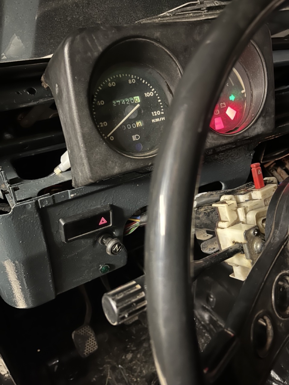
Let's start with the good stuff: all idiot lights are back in action, even after fitting a new ignition barrel.
But the tail-lights remain somewhat elusive. So as a first measure, let's replace all the old and mostly mismatched fuses in the fuse box. (Polite hint towards the previous owner(s) - a correctly chosen fuse could have saved you from burning up that ignition barrel...)
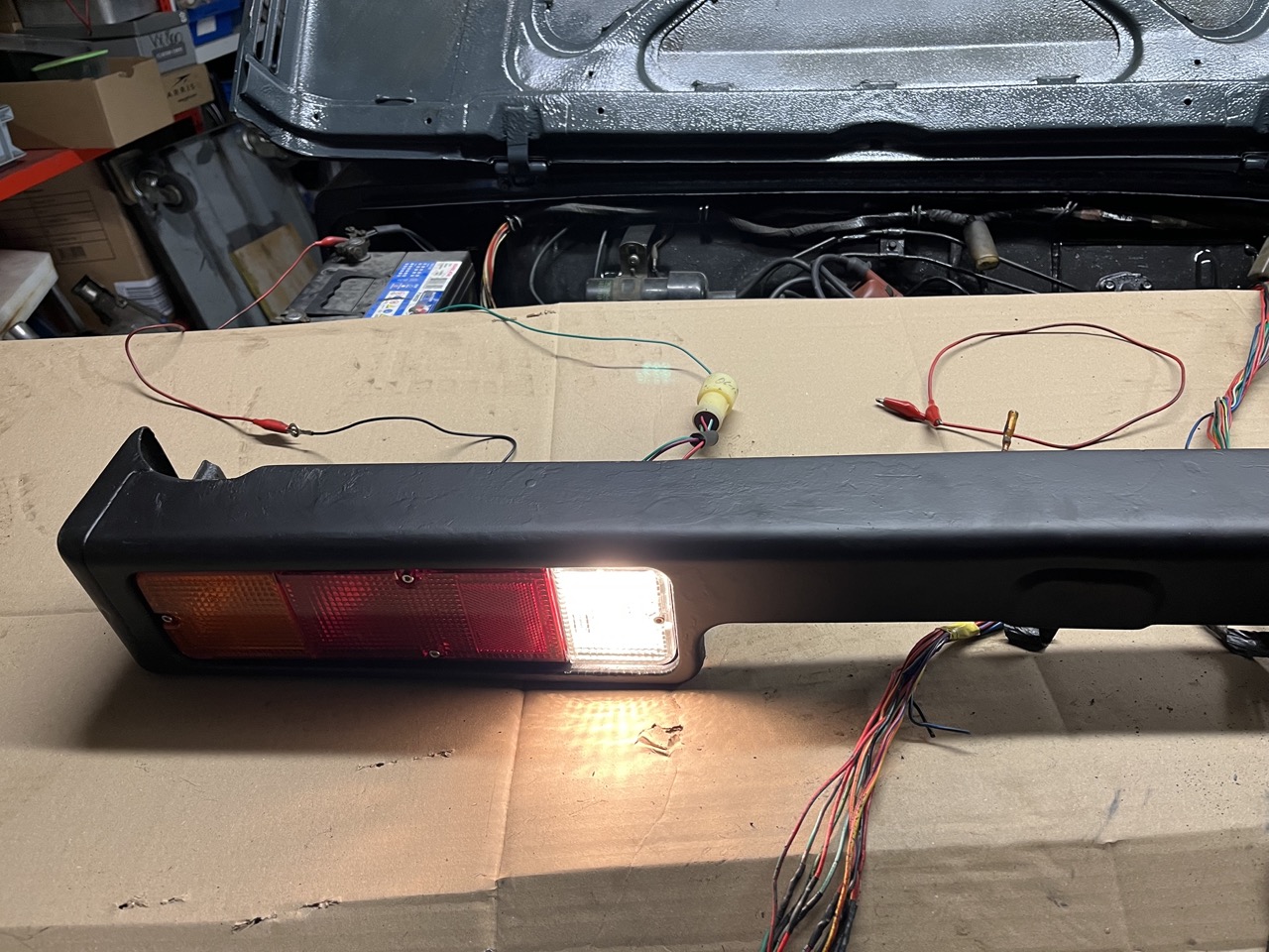
Rear fog light cable was a bit worse for wear.
Then here's a bit of a speciality of the 1983 and 1984 SJ410s as they had to have an additional warning light for the diff-lock and 4WD mode. Unfortunately all the holding tabs were broken off, so generous amounts of hot glue now keep this one in place.
Whilst rummaging under the dashboard I found a (broken) trailer light relay that was causing serious issues with all the switch gear.
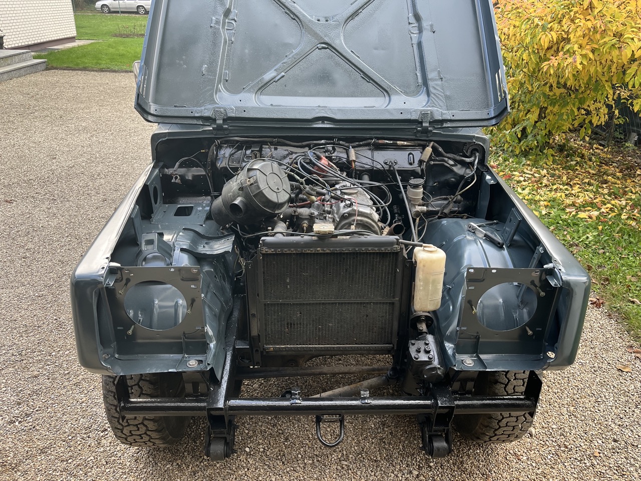
With it removed the front lights started to working again as intended, but nothing on the back.
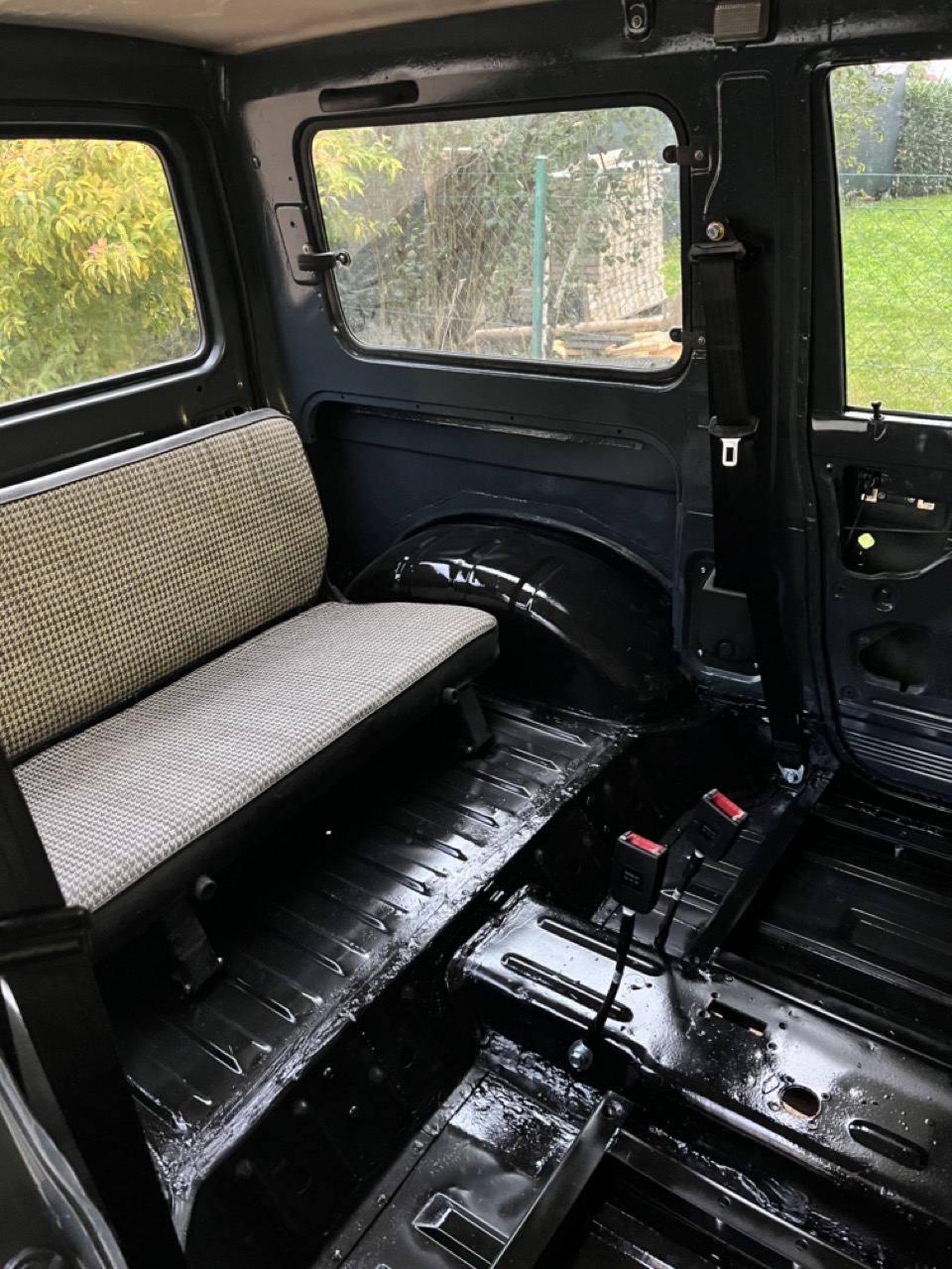
Continuity testing my way quite literally from the taillights forward, if the stop right above the gearbox where I had to repair the transmission tunnel in a few spots and had cut out some rusty metal.
Using up what was essentially my complete supply of alligator leads, I was able to reconnect all connections and proving that even the issue with the diff-lock warning light was related.
Except all of this was a bit weird... because the Diff-Lock wasn't engaged and the switch shouldn't have triggered and why did I have no reverse lights?
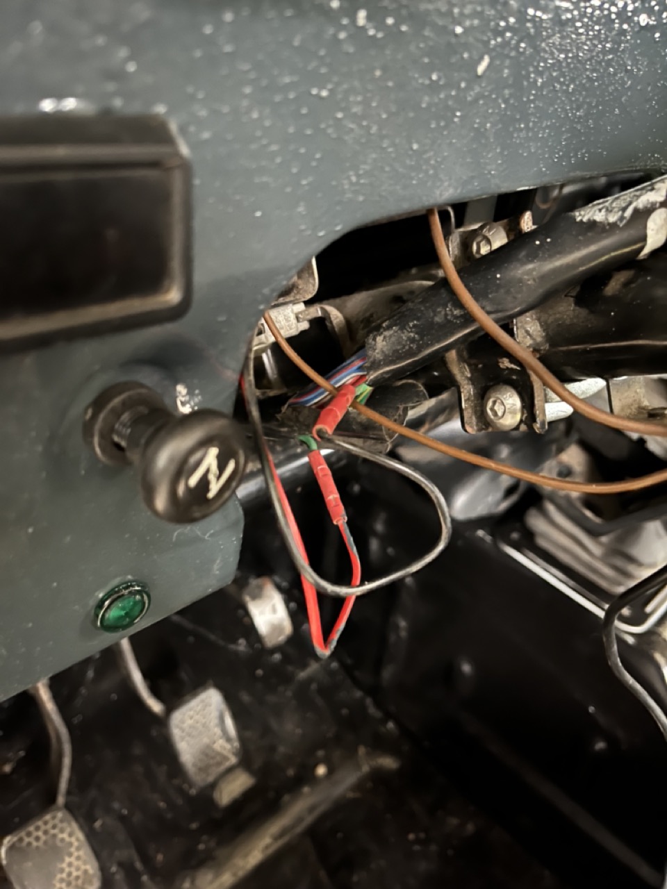
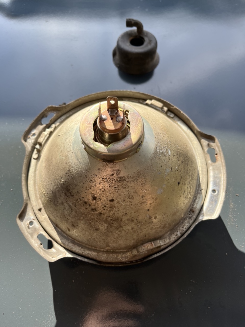
Luckily it wasn't too hard to pull out the whole rear light loom to the front and find out what's wrong with it.
It wasn't neither the bulb or the taillight...
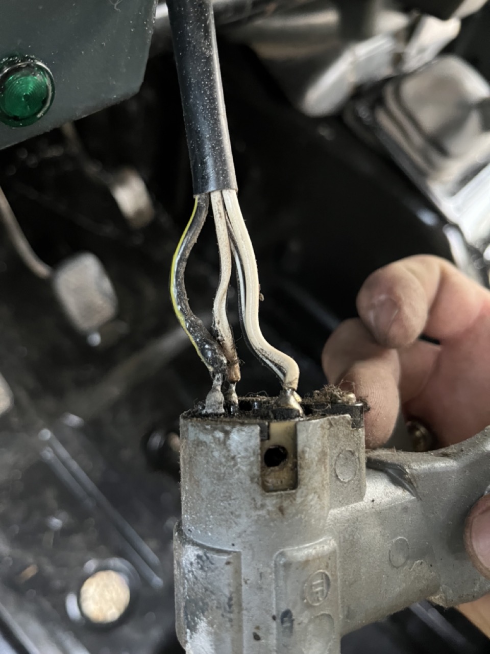
... it was one of those cases of bad luck (and bad design). As the diff-lock and 4WD warning lights were afterthoughts for specific markets in Europe, apparently nobody bothered much to check whether the wire colors were already in use or not. Turns out I mixed up two cables and the permanently live diff-lock warning and the switched via ground reverse light switch both use the same wire colors.
Believe me, when I say that this felt like a very, very long weekend until I found the fault.