Sunday 28 February 2021

The XV side - it's a sidecar, sort of... (part 7)

Last time we left off with having cut a huge gaping gash into the rear frame tube to finally make the rear mount adjustable again. So at first this had to be welded up again and then the inside ground flat again.


The amount of loose rust that came out was more than impressive though.

A 40mm flap wheel was the perfect tool in the end to get rid of the weld slag that had built up on the backside and remove a bit more rust on the inside.

In order to work out, how everything will be going together, I had to weld on the final bends, which gave me the opportunity to finally do some thin-wall stainless TIG-welding again. 


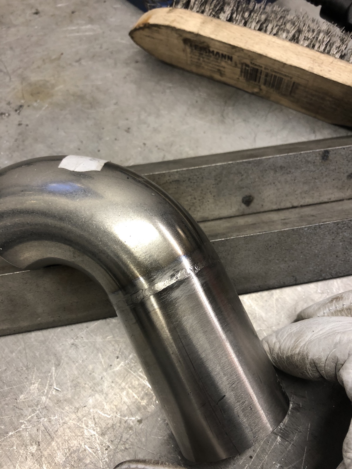
By the way did I mention that it was a bit fresh in the workshop?

After all of this it was well about time to lay out and make the mounting hardware for the rear sidecar mount.


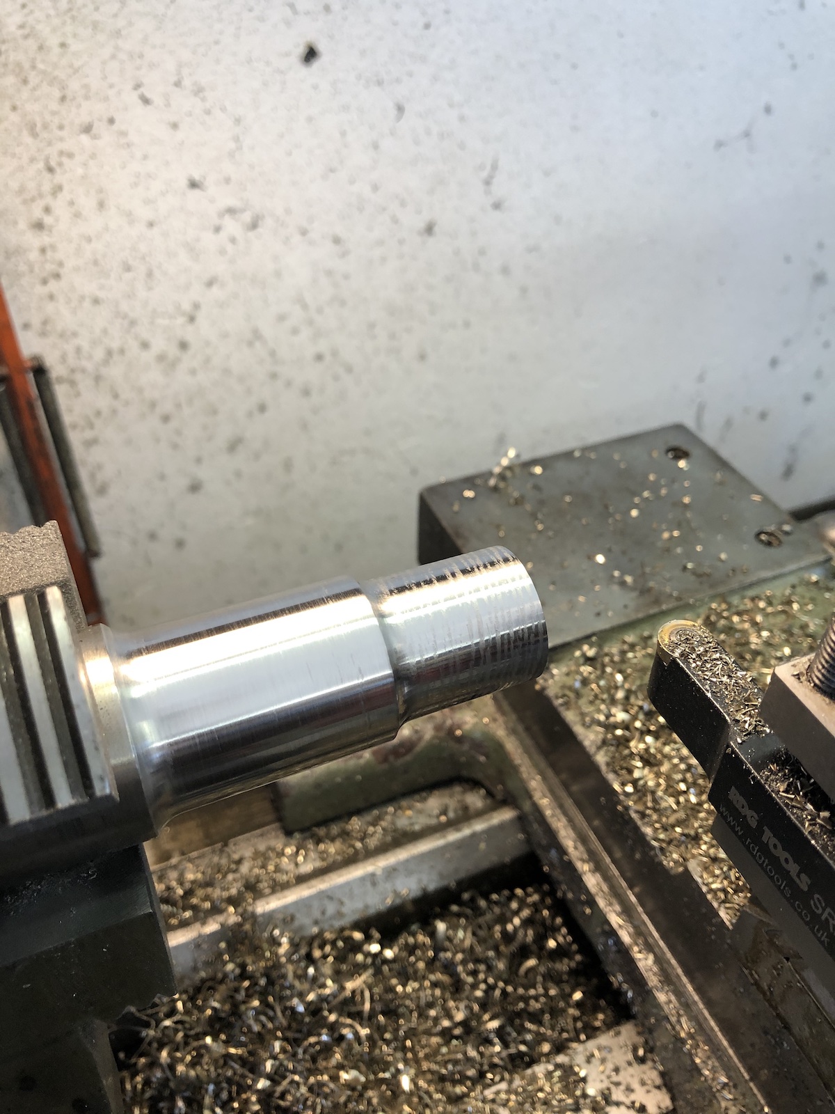
Stuff that makes the engineer happy: when you hit that number WAY closer than planned.


As the tube in the frame I was going to use, was 14.odd mm in diameter, I made two bushes to get it down to spot-on 12mm.


Obviously I needed a long enough bolt, which started out as a bit of all-thread with a nut welded on.

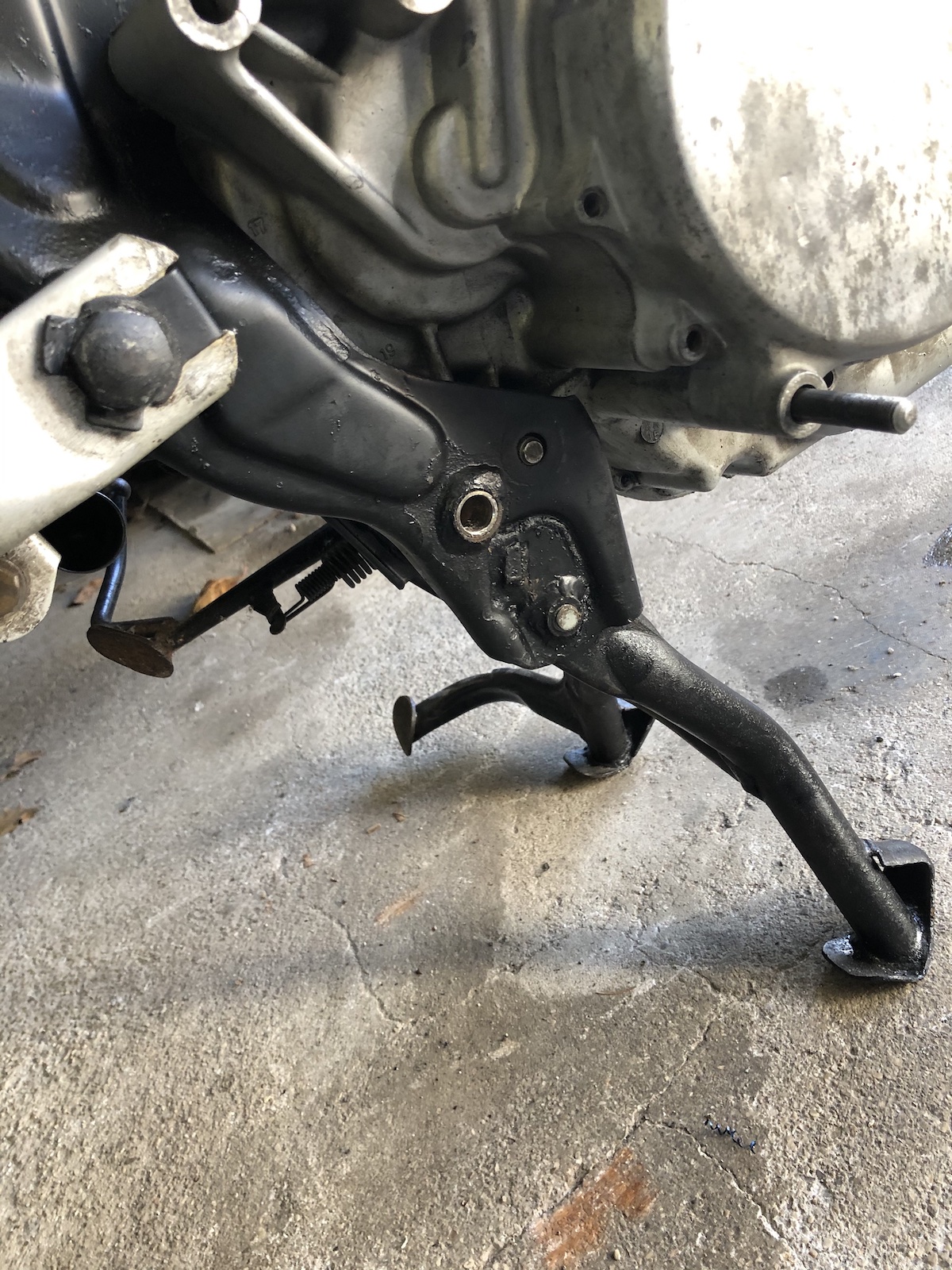
Then (for the umpteenth time) the sidecar step fell out of its box and I decided to get the snapped stud out and fit it up to the sidecar-frame


After this very welcome intermission, I started again on making that rear mount. First of all it needed an M10 thread in the back, so I could take it off during the numerous mockups. (So I thought - never had to take it off even once.)

The turned parts were done to a light interference fit, to limit the number of hands needed to make everything line up.


Nice... this sits right next to the rear wheel and with this amount of leverage it'll twist the lower subframe into a pretzel in no time. 


"All the amps" were applied and the rear mount lengthened by about 130mm. Bonus: it now can sit a bit higher as well as it doesn't have to clear the muffler anymore, but only the exhaust pipe. Which is another few milimeters gained. 


Shortened and welded the rear mounting tube and "pinned" the mount (for future-welding) with an M8-bolt to the backplate.

It will do for rolling it around in the workshop, but not much more without welding, but it will definitely make triangulating it a lot easier.

The last bit that I turned my attention to this time was the front top mounting point. Now I had a lovely clevis mount, but unfortunately it was male (externally threaded) and I wanted to use the long bolt connecting both top-mounts and as such, needed the female version of it. A nut with a clevis, if you would like to see it this way. 


Unfortunately I didn't manage to get it milled in time for this post.

So, the next step is to turn the old girl into a roller and maybe (while we're at it anyway) make the upper rear mount and then find out how to do the exhaust routing, fit the footpeg-backplates and work out how to run the front downtubes.

Sunday 21 February 2021

New motor (again) for the old Rhino- / Coronet-Lathe

 ... now with even less RPMs. I guess I should this one from the start and not somewhere in the middle - Last Summer I replaced my lathe's motor (found here), with a 2.2hp/2800rpm unit, as I hoped that with higher RPMs and more importantly more oomph (2.2kW instead of 0.75kW) I would be able to finally get the sort of finish out of the machine, that I knew it was capable of. What I did achieve was to heat up the roller bearings, but not much else. As I have little intentions to ruin the old girl, I recently bought a decent 1.5kW/1400rpm motor. 

First things first, the motor had to be set up to run in CCW - and I was pleasantly surprised to see two VERY proper capacitors.


Thanks to a label in the motor cover wiring it up was a 15-minute job.

The pulley came off with (relative) ease and went on onto the new motor in the same fashion.

And now it's a proper self-contained unit.

The thing that actually fought me the better of at least two hours, was to redrill/slot the mounting holes and even more so re-install the motor-tray, without removing the main spindle from the lathe. (I now have a lovely reminder on just how sharp those gears are on one of my hands!)

With (oversized) slots the motor now fits nicely and can be tweaked so the belt runs straight and true.

 Also the new motor sounds a lot less rattly, compared to the old one. 


What's the verdict: If I had mounted the old 2800rpm motor the same way as this one, the results would definitely have been nicer. It would not have solved too-high-rpm issue though. A tad under 1100rpm should still work nicely for most tasks though. By the way the old motor will be turned into the drive for a new massive belt-sander, that I have had in my mind for a looooong time.

Monday 8 February 2021

The XV sidecar - making the rear sidecar frame mount submit to my will (part 6)

In order to know how to proceed with the rest of the build, especially to find out where the rear sidecar mounting point would go, I had to permanently affix the front mount to the engine. To be fair it only needed another spacer, so I have something to connect my downtubes to. 

50mm long, 10mm hole in the middle, it's not quite the sort of stuff one would need a drawing for.

Soviet engineering from the 1980ies basically only knows two states - making "brackets" from 4mm (or thicker) bandsteel and essentially hotgluing on bits with a welder. This was the later. The mandatory "that's not going anywhere" was muttered and all should be good. 

Would you look at that, just as I suspected, the rear attachment point kisses the silencer. 

I'll J-U-S-T ... Q-U-I-C-K-L-Y adjust it. 

Elongated the slot in the frame, heated it with an oxy-set and used a 2m extension on a 1.5m breaker bar and jammed a screwdriver into the cut in the tube to splay it out.

Then I quickly fitted a longer rear-shock and took the footpeg-plate off to get an idea, whether the bolts hidden underneath would lend themself as mounting points for the subframe connector plate(s). 

Last picture shows: it was rusted in solid 10cm into the tube.

The "quick" adjustment took the better part of 2 hours (and as can be seen in the picture), it got dark and that was it for the day. Not entirely sure whether the next step will be to get started on the exhaust or continue with the subframe as both want to inhabit the same space underneath the bike, but as I can lower the subframe, but the exhaust is pretty much a given, I guess this anwered the question already.