Showing posts with label tools. Show all posts

Wednesday, 9 March 2022

Public Service Announcement: Bosch LSU 4.2 for APSX WB2

 A friendly public service announcement for those, who run an APSX wideband sensor for tuning: The single most vanilla Bosch Wideband Sensor (LSU4.2), made for a plethora of models from the VAG group and fitted to all sorts of Audis, VW and Seats (and if you're looking for it at the breaker's especially in 1.8T models), Bosch part no.: 0 258 007 351 is the one you need to get your APSX gauge working again, once you killed your wideband sensor...

I paid for mine 75 Euros (new), but if you can get one from a breaker, you'd probably pay a fraction of that...

Tested myself and working like a dream. You're welcome. 😏

Monday, 8 November 2021

The SR500 sidecar build - Boring (part 5.1)

... holes and making a boring bar that works with insert tooling. If you have a boring bar, most likely of Far-Eastern provenance, you will have encountered them - import boring bars, with their little (usually dull) carbide inserts soldered on. Now one can work with them rather well actually, with some rework on the bars with a diamond file to make the inserts resemble some sort of a cutting geometry and some very, very light cuts one can get some pretty good results with them. But with the task at hand of pushing what the 6x26-mill can take in terms of cutting and doing a lot of it, this quite literally won't cut it. 

As this isn't quite my first rodeo, in the past I got a cheap boring bar and modified it as below. Unfortunately (for this boring bar), I no longer run TCMT16 inserts on my lathe and thus would have to buy inserts solely for this one bar. Not very economical, especially as I have a ton of CCMT09-inserts.

So this one started it's life as a 16mm, right handed boring bar for CCMT09 inserts. I shortened it to a reasonable length. (The shorter, the stiffer and more stiffness means less vibrations and that in turn means a better surface finish.) Then turned it down in the lathe to fit the boring head. In my case this meant going down to 12mm. Also this is where cheap boring bars shine as they are made from some butter-like alloy and turn beautifully on the lathe. 

At this point, one could go ahead and just use it, but every time you install it, you'd have to clock it to get it right on center (or actually a bit below) again. So I put it in the mill and made a little flat spot to register against. 

And there you have a boring bar where you can burn through inserts and not care much about it.

Oh and burn through inserts... I did not. For five holes, which resulted in enough swarf to fill up the whole vice and pile up left and right of it, I had to change inserts once, because it got a bit dull.

Sunday, 21 February 2021

New motor (again) for the old Rhino- / Coronet-Lathe

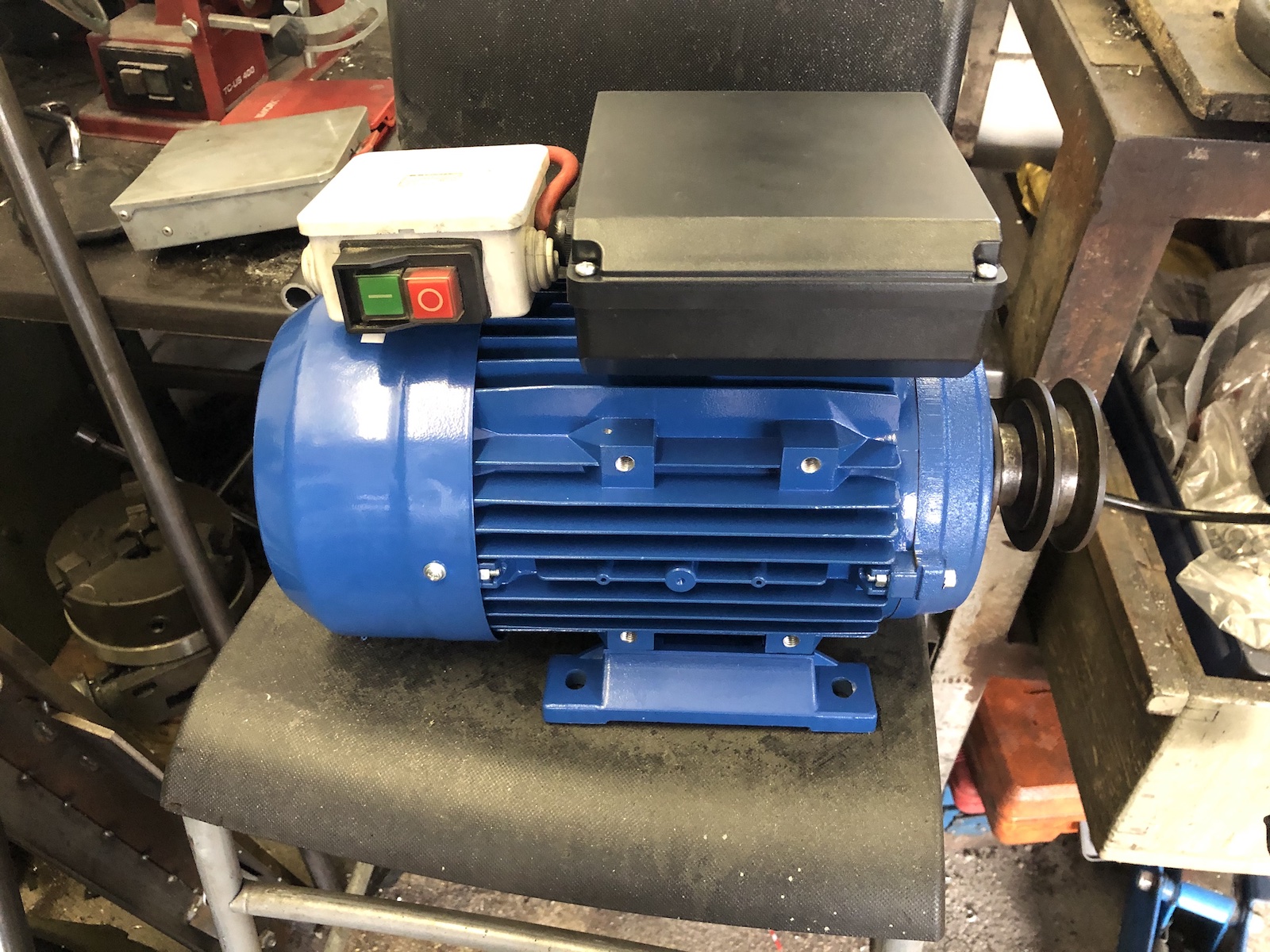
 ... now with even less RPMs. I guess I should this one from the start and not somewhere in the middle - Last Summer I replaced my lathe's motor (found here), with a 2.2hp/2800rpm unit, as I hoped that with higher RPMs and more importantly more oomph (2.2kW instead of 0.75kW) I would be able to finally get the sort of finish out of the machine, that I knew it was capable of. What I did achieve was to heat up the roller bearings, but not much else. As I have little intentions to ruin the old girl, I recently bought a decent 1.5kW/1400rpm motor. 

First things first, the motor had to be set up to run in CCW - and I was pleasantly surprised to see two VERY proper capacitors.


Thanks to a label in the motor cover wiring it up was a 15-minute job.

The pulley came off with (relative) ease and went on onto the new motor in the same fashion.

And now it's a proper self-contained unit.

The thing that actually fought me the better of at least two hours, was to redrill/slot the mounting holes and even more so re-install the motor-tray, without removing the main spindle from the lathe. (I now have a lovely reminder on just how sharp those gears are on one of my hands!)

With (oversized) slots the motor now fits nicely and can be tweaked so the belt runs straight and true.

 Also the new motor sounds a lot less rattly, compared to the old one. 


What's the verdict: If I had mounted the old 2800rpm motor the same way as this one, the results would definitely have been nicer. It would not have solved too-high-rpm issue though. A tad under 1100rpm should still work nicely for most tasks though. By the way the old motor will be turned into the drive for a new massive belt-sander, that I have had in my mind for a looooong time.

Friday, 31 May 2019

Rotabs make the mill go round...

... or how to fit a 190mm chuck on a 150mm (6") rotary table. In reality it is quite easy: make a backplate, fit it on the table. Done.

It's the details that make jobs like this tricky. Originally I attempted to make the backplate entirely on the mill, but the surface finish was rather dissatisfactory.

So first step was to get both sides parallel with each other and correct a spot, where the mill had eaten into the step.


The top side needed a bit of attention too, the M6 bolts are plenty to hold the adaptor to the rotary table. 


Should you happen to know the brand (most likely Soviet-era Ukranian made) or where to get a set of internal jaws for it, please let me know.


The countersunk allen bolts needed a bit of touch up to clear the locking handles in the vertical and a reduction of diameter to reduce the size hole needed to be countersunk.


Vertical runout after all this jazz: 0.02mm between highest and lowest spot. 


I admit, it's quite a bit higher than I had hoped, but to be fair it is massive and it will be perfect for what I have in mind for it. That being said, it might be replaced with two smaller 125 (5") chucks that I have left over from my old Myford. So if you're in the market for a ready made solution for a 6" rotary table...

Friday, 8 February 2019

Syncing vacuum gauges

I have a suspicion that I know, what you're thinking... shouldn't that read as "syncing carbs/throttle bodies WITH vacuum gauges"? Well, not if you have had a little backfire through the carbs and that properly messed up your gauges.

Now here is the moment, when you realise that you bought tools from a reputable manufacturer, if you can simply buy spares (in this case a new set of clcoks 15 years after you bought them) and they'll basically overnight them to you and respond to your emails at absolutely ungodly times of the day, i.e. late in the evening.

Let's have a little look at this picture, do you see what has gone wrong?


There are copper-beryllium springs inside these gauges, which are very sensitive to even the slightest changes of vacuum (or pressure). Unfortunately these don't take very kindly to being overstretched in either direction. A good indicator is for example #4 which doesn't sit at 0 anymore.

After parting with quite a handful of my hard-earned (definitely more than for a cheap set!), I received four new clocks which had (slightly) adjustable scales.


As you can see with the attached y-piece, in order to sync them, two (or more) gauges have to be hooked up to one vacuum port and then adjusted to show exactly same value.


Which in the end looks something like this and once again proves that sidecars absolutely rule as mobile workbenches. 😀

A quick word on the elephant in the room: Why didn't you just get a set of cheap... Simple really, you can only adjust carbs as accurately as your tools will allow you to measure pressure differences, so the more accurate, the better the job. To be honest, the level of accuracy that can be achieved with these is (usually) absolute overkill, but the other thing about cheap gauges is that you can't sync them to each other inducing another error aside from the already given inaccurracy aside from a less sensitive spring. Also: it's nicer to know you could absolutely nail it and then call it good enough than the other way round. 😏

Saturday, 5 May 2018

Tooling up for the TR1 engine build - fly-cutter

Amongst the things I need to get the new hopped-up TR1-engine working, is a means to re-surface the cylinder heads after welding them up. As I don't own a large surface grinder, a fly-cutter is the means to an end.

First up was a chunk of 110mm diameter tool-steel, that was squared up on both sides and then center-drilled.


The future-shaft was made to a hefty press-fit and then, as the thought of a roughly 5kg fly-cutter arbor flying off through the workshop gave me a "slightly" uneasy feeling in my stomach, I decided to additionally TIG-weld it. 


Once it was welded up, it was put back in the lathe to turn it down to final dimensions and also decrease the amount of potential wobbles. 


After some thinking, I decided to decrease the overall mass by milling both sides flat. (Which incidentially also made tapping for the set screws quite a lot easier. 


The result is pretty acceptable, especially when considering that this was done on a flimsy RF-25 roundcolumn mill. 

Sunday, 2 April 2017

New favourite tool - and a Jawa (Velorex) wheel bearing swap for 17mm axles

As some may know, stock Velorex 560 and 562/700 sidecar axles are puny 15mm items. Which I suppose is totally fine if you bear in mind, that the original Jawa 350 put out 12 hp and even the final Jawa 350 models were in the low 20ies. Now even a restricted SR500 is 27hp and an unrestricted one is at least in the low 30ies. As a result, I swapped out the axle years ago for an old XS400 rear axle and fitted an XS400 rear wheel to the sidecar (thus also increasing the wheel-size to 18").

The new owner of my sidecar also bought a set of wire wheels for those... pretty moments, because to be honest, the cast wheels are very functional, but that's about the end of the story really.

Luckily there's also 6302-bearings with a 17mm inner cage. Swapping out the old Jawa bearings was slightly overdue though.

The first hurdle that has to be overcome is this aluminium cover, which covers the sprocket-drive on the wheel. It just has to be pried off. Normally they are rattly and loose - this one wasn't.


And here it is, my new favourite tool: a 3 Euro hotplate for heating up hubs and bearings. Works an absolute charm as it heats up the parts very evenly. 


Slightly crusty original bearings... 


The only tricky part is this clip that retains the bearing and is usually hid under a stupid layer of crud!


Proper new double-sealed 6302 (17mm) bearing.


And there you have it. The only part missing in the pictures is the part, where I drill out the center-tube to 17mm...

Sunday, 1 May 2016

A very basic Turbo 101


Now this is meant to be a very basic Turbo 101, mainly to explain the ways I moved along to decide to move from a blow-through to a draw-through setup.

Below you see a very simple schematic on how a turbo works including a dimensionally incorrect depiction of a wastegate.

In essence a turbo is an exhaust gas driven pump, which will push in air (blow-through) or air-fuel-mix (draw-through) into the engine. The wastegate is meant to limit the turbine speed and hence the created pressure inside the combustion chamber (aka "boost"), by venting a part of the exhaust gas straight into the exhaust.

The most simple design to build is the so-called draw-through setup. This is pretty much where the upsides end unfortunately. With the turbo compressing the air-fuel-mix there is no room for a plenum, which would buffer the alternating demand for fresh air(-fuel-mix), which makes the engine react relatively sluggish on throttle changes. Additionally due to the explosive nature of the air-fuel-mix it is impossible to use an intercooler for charge-cooling thereby limiting the amount of boost an engine can take as intake temperature and pinging are directly related. Another issue is part-throttle response. With the carburettor being placed on the inlet-side of the turbo it will never actually see boost and therefore can only be tuned according to the vacuum created on the inlet-side. This works quite well off-boost and in wide-open-throttle situations, but not so well anywhere else. One can get around this to a certain extent by using a CV carb, which is also a reason, why one can see SU-carbs on so many draw-through setups as the throttle slide lift is directly related to the vacuum. One final let down has to be mentioned though, in order to build a draw-through setup a carbon-sealed turbo has to be used or a conventional turbo has to be retrofitted with a carbon-seal. This basically leaves you with two choices: Get an old Rajay-Turbo (where it is quite to find parts for) or buy a China T3-Turbo as I did and live with the fact, that the overall quality may leave a bit to be desired.

Nevertheless, the system is easy to build and in 1/4-mile applications (or the like) there's still room for this setup. The lack of intercooler could at least be partially offset by using water-methanol-injection for charge cooling.


The blow-through setup is way more sophisticated. Here the carb is placed between turbo and engine. With the turbo only pumping air, the usage of intercoolers for efficient charge cooling is possible. The tricky part with this setup lies in the fact, that the carb actually sees pressure. This subsequently leads to several other requirements: First the fuel has to be pressurized to a pressure-level slightly over boost, which means a fuel pump and a rising rate fuel pressure regulator are necessary to take care of that. Secondly the float bowl has to be pressurized to slightly over boost-pressure as otherwise fuel may be squirted out of the jets, but it would really only be fuel in depending on the boost level. This is where the so called pitot-tube comes into effect (there will be a separate post on this subject as it is HUGE). Now bearing in mind that a blow-through setup requires all this extra tech, there must be a benefit for both the manufacturers and consumers in the end? As the carb's fuelling is directly coupled to boost-level overall fuel consumption is drastically reduced (and therefore also meeting emission requirements is made a lot easier!) Additionally with the usage of a plenum a reservoir for pressurized air is available making meeting the engine's air requirements a lot easier and as a result smaller turbos can be used to achieve similar power levels as before. Thereby reducing turbo lag and speeding up spool-up. And if that weren't enough unlike on draw-through turbos, where a piston-ring type dynamic seal can be used, which incorporates a lot less drag adding to the efficiency of the turbo.
The last part mentioned in the schematic below is the blow off valve (B.O.V.), which vents boost pressure into the atmosphere to keep turbine speeds up for a longer time, even when the throttle is already shut.


That said my original setup is/was a blow-through setup. It is in my book the perfect choice for a well refined turbo setup, ideal for road use.
Unfortunately as mentioned before the setup is very complex and the amount of space available on the TR1 is rather limited.

As such, I decided to take a u-turn and restart the build with a draw-through setup. Especially bearing in mind, that the main usage of the Turbo TR1 will be on the dragstrip.


Wednesday, 23 March 2016

Some general tune-up and and welding a bung in for the AFR-meter

Recently I was asked on a forum, what my stealthy VM38 setup looks like, which coincided very well with some re-jetting work.

 One of the extremely convenient aspects of VM38 carbs is that you can in fact change the main-jets without removing the floatbowl. Unlike when you want to change the pilot jets as they are countersunk in an orifice.
 VM38s sport a brilliantly unique float arrangement.


Bungs for AFR-meters can be bought via various sources. So called Lambda-probes usually sport an M18x1.5mm thread (there's a smaller M12 based version as well, but these are less common!) Usually these rings are around 25mm in outer diameter with a lip, which is a tad bigger. 

 Mark a suitable spot on your down pipe and remember that the Lambda-probe should be angle downwards, so that potential condensation won't pool up inside the probe.
 Drill an as large as possible hole (my biggest drill was 17mm) and then use a die-grinder. Once you're getting close check all the spots where the bung and the pipe touch, the better the fitment, the nicer the corresponding weld.

 Not exactly the nicest weld in the world. :-)
 Oh and a word of warning: NEVER fit a cold plug into a hot threaded bung. Feel free to guess how I found that one out.
 And installed again on the everyday TR1!