Showing posts with label milling-madness. Show all posts

Saturday, 27 January 2024

Rotary table gets a new 125mm chuck

 So, if you have a mill at some point you will want a rotary table, because they are stupidly handy. The downside to a good rotary table is usually the size and thus the weight. So if you have for example a 150mm (6") rotary table and fit a 190mm chuck on it, you don't have to do any more weight lifting for the day. This among the other fact that I only had external jaws for it, drastically limited its usability for me. Add to that that I have been a very good boy, so I treated myself to a new Chinese 125mm chuck.

Originally I thought I'd make a completely new adapter for the chuck, but after having a very long look at it, I decided that with some precision lathe-work I could not only modify, but improve the base-plate and also have an excuse to let the little engineer inside of me out.

So how do you hold a 200mm plate in a 125mm chuck? The trick here was super simple by using an 8mm allen head bolt and use that as a datum/reference for all other work. Interestingly enough in the first picture the surface finish looks absolutely terrible, which it isn't at all in real life.

Not only did I machine the chuck face, but also the back side and unlike in the past, I now have two alignment edges, in the center it will locate into the morse tape in the rotary table and also on the outer edge.

Now I don't want to pat on my own back too hard, but that chuck registered on the hump in the middle like you wouldn't believe. Just downright perfect.


Three M8x70 bolts, a bit of tapping and countersinking later and there you go.


So why the rush you ask? First of all I will need it make a few of the parts that I want to make for the Hotroad TR1, specifically cut some hexes onto shafts and more immediately, the little green pickle has got almost new front brake disks on it (seriously), but as it was parked for so long the pads rusted to the disks, so giving them a skim is the order of the day.

Thursday, 18 May 2023

Everyday TR1 - two ways of not fixing the oildrain and a third one that actually worked

 Oilchanges - not much to it: drain the old oil, swap the filter, fill in new oil. As I said not much to it. 

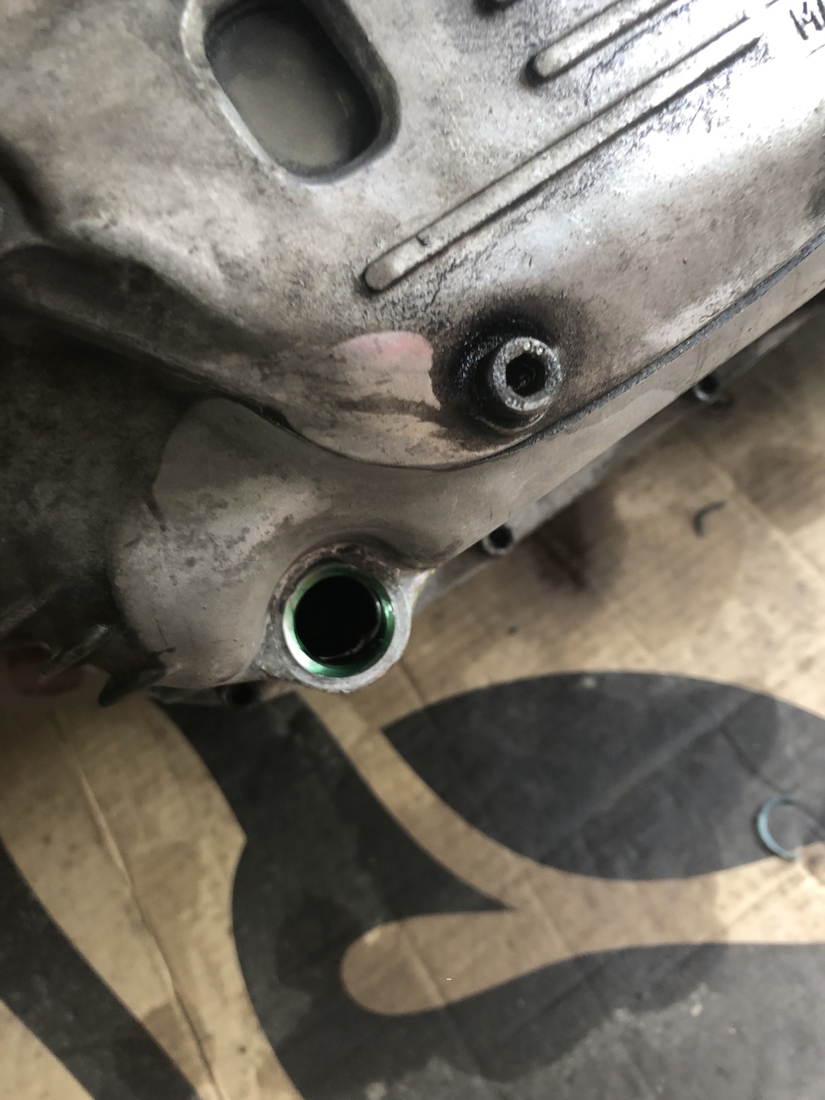
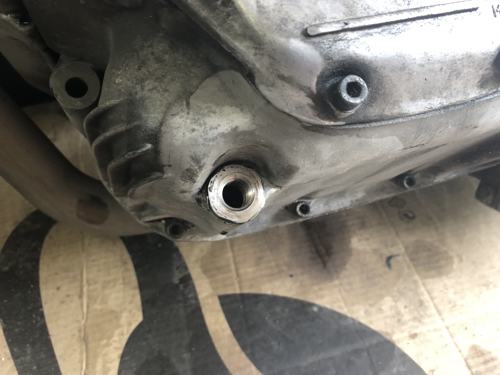
What you see here is almost to the day last year's attempt in fixing the stripped thread of the drain-plug. As the very astute amongst my readers might have noticed that's both the thread insert AND the drainplug coming out in one piece. I traced this back to two specific issues during installation: first, I used medium strength thread lock and second I only tightened the insert by hand and solely relied on the thread lock to hold it in place. 

As a result two areas of improvement have been identified, the first one being the use of high strength thread lock and second come up with a means of torquing the insert down to a level that ideally exceeds what the drain-plug will be installed to and only use the high strength thread lock as an additional level of safety.

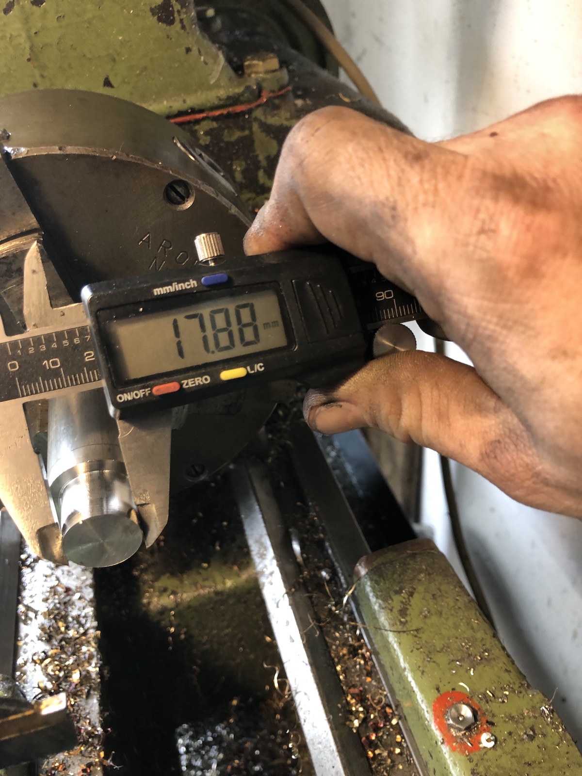
With the threads on the old plug being a bit chewed up anyway, I went ahead and made a new one from stainless. M18x1.5 on the outside and M14x1.5 on the inside. Overall length 20mm, with 16mm of M18 thread.


Which put me pretty much where I ended up with the old insert and meant next was the need for a decent way to torque it down. 

So my first idea was to mill a hex onto the head in order to be able to torque it down this way.

Used some paper to protect the threads and countersink it/remove the burrs from parting off.

The finished product.

So after some very, very thorough cleaning of the thread in the engine case, copious amounts of high strength thread lock were applied and the insert installed. 


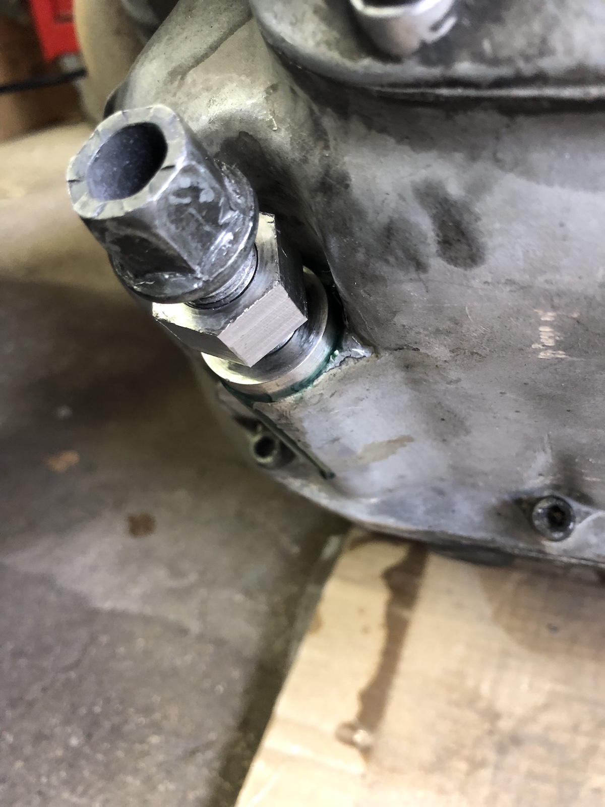
As you can probably tell, there's not exactly a lot of room around that hex to torque it to spec. So I sacrificed one of my cheaper 22mm wrenches and milled its jaws down to fit. 


As you couldn't really make the hex-head any smaller, because some surface area is needed for the copper washer to seal against the idea was then abandoned. M14x1.5 is a weirdly specific kind of thread, for example spark plugs use it, but also wheel studs and -bolts of a lot of German cars do.

So another threaded insert was made...

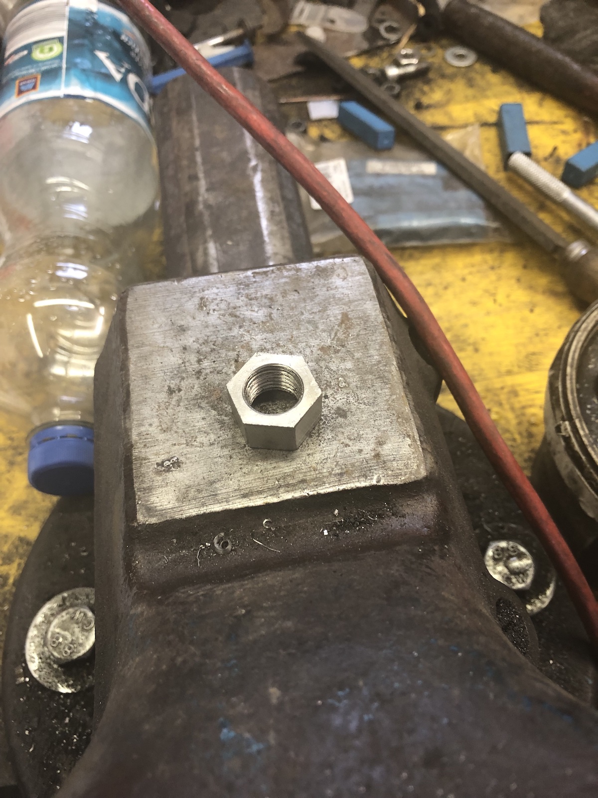
... and in order to turn this into an installation tool a M14x1.5 locknut had to be made. (Impossible to buy locally.) In a first step, I milled two flats onto the "nut" in order to be able to tighten it down onto the wheel bolt.


Followed by milling it to a 20mm width hex.

The finished nut, after some touch up with a file.

The picture below should also give an idea why I decided to make the lock nut so tall. In order to install the whole lot, nut and insert are threaded onto the wheel bolt and locked down with the nut and bolt. Then use the head of the wheelbolt to thread it in and tighten it down PROPERLY (assisted with some high strength thread lock).

Hold the bolt still (which is why you have to do this immediately, before it starts to cure) and undo the nut and simply wind out the bolt. As I gave the whole lot a good tug (far more than I would tighten down the drain plug) and the high strength thread lock should add another 30 to 60NM of break away torque, I'd say this is rather likely to work.


... and it did. Check out the witness marks on the two photos below.


 So why this somewhat "elaborate" solution and not just go with a M18x1.5 drain plug straight away? (common on a lot of cars) First of all the 40 year old ally is pretty tired by now and in case this thread failed again, there wouldn't have been any material left over for a more oversized (and still at least half-way common) thread. Additionally despite my best efforts, I somewhat doubt that the M18 thread in the engine case is perfectly perpendicular to the mating surface given the fact that I had to drill it free hand. An undoubtable benefit also lies in the fact that from now on a steel bolt is threaded into a stainless steel drain and thus this would in theory allow much higher torque and no more wear on the well aged ally.

Tuesday, 21 December 2021

The SR500 sidecar - finishing the mounting blocks (part 8)

Last time I wrote about the sidecar mounts, I was pretty convinced that they are more or less done. Yup, when going through that last post on sidecar mounts (part 6), I had a good chuckle myself. 

First order of business - make the parts look a bit better and chamfer them. Technically completely superfluous, but visually appealing. (And if that's the sort of eye-candy needed to convince the engineer that those are some well made clamps - which they are - then heck, let's do it.)


As I decided that I would never again fit the bash plate anyway and it would allow me to mount the lower mounts a bit higher up, the tabs for the afore mentioned guard had a date with Mr. angle grinder. 

As my sidecar mounts are (intentionally) a bit beefier than the original clamps that originally were on my first SR500 sidecar, the engine had to be unbolted and lifted up a bit in the frame to squeeze the mounts in.

To be honest that wasn't enough and 3mm had to come off of the back side of the clamps. A 50mm knife head makes short work of that.

When fitting the mounts I remember a little detail that annoyed me on the last SR500 sidecar conversion:  The two outer bolts are easy to reach and tightening the nuts is no problem, but the two inner ones...

... as such I threaded the clamps for M12-bolts and now can comfortably tighten them from the front.

Squeezing the rear mount in between airbox and frame required the same mods aside from me having to cut out the splash guard.


The astute amongst the blog readers will have notice the absence of the top mount with its puny M6 bolts holding the two halves together. Well that's currently sitting on the mill getting drilled out to M10, after being dramatically slimmed down as it looked both disproportionate with no particular gains in terms of stability.


 The big lesson learned here was - high quality wood routing bits are awesome for chamfering (or rounding corners, if you buy the right bit) and it's not the end until you're done. Also... can I weigh in swarf? The last picture gives a good indication what my workshop floor looks like at the moment.


Monday, 8 November 2021

The SR500 sidecar build - Boring (part 5.1)

... holes and making a boring bar that works with insert tooling. If you have a boring bar, most likely of Far-Eastern provenance, you will have encountered them - import boring bars, with their little (usually dull) carbide inserts soldered on. Now one can work with them rather well actually, with some rework on the bars with a diamond file to make the inserts resemble some sort of a cutting geometry and some very, very light cuts one can get some pretty good results with them. But with the task at hand of pushing what the 6x26-mill can take in terms of cutting and doing a lot of it, this quite literally won't cut it. 

As this isn't quite my first rodeo, in the past I got a cheap boring bar and modified it as below. Unfortunately (for this boring bar), I no longer run TCMT16 inserts on my lathe and thus would have to buy inserts solely for this one bar. Not very economical, especially as I have a ton of CCMT09-inserts.

So this one started it's life as a 16mm, right handed boring bar for CCMT09 inserts. I shortened it to a reasonable length. (The shorter, the stiffer and more stiffness means less vibrations and that in turn means a better surface finish.) Then turned it down in the lathe to fit the boring head. In my case this meant going down to 12mm. Also this is where cheap boring bars shine as they are made from some butter-like alloy and turn beautifully on the lathe. 

At this point, one could go ahead and just use it, but every time you install it, you'd have to clock it to get it right on center (or actually a bit below) again. So I put it in the mill and made a little flat spot to register against. 

And there you have a boring bar where you can burn through inserts and not care much about it.

Oh and burn through inserts... I did not. For five holes, which resulted in enough swarf to fill up the whole vice and pile up left and right of it, I had to change inserts once, because it got a bit dull.

Wednesday, 9 June 2021

6x26 mill - bolted it down properly and made some swarf

 Last time I admittedly didn't have time to actually try out the new mill, which among other things was down to the fact that the mill wasn't bolted in a way that would have made me feel comfortable to work with it.

The main reason being that the previous mill was being held on with some bits of M12-allthread with nuts on both ends. With the new mill's baseplate being a bit bigger, I had to resort to lobing off "a bit" of the bolt head, so I could fit them. On the upside, tightening the nuts needs no spanner on the underside as they rest against the frame. 

What you see in this picture is a an XV1100 clutch basket being modified for use in my new XV-sidecar. The extra breakout is to improve the oildrain, to allow for quicker shifts. (But more on that - and it will be a lot - in the next post on the sidecar.

But what most of you will be most interested in, how does a Taiwanese 6x26-mill stack up against the old RF25 or a proper industrial size toolroom mill, e.g. a Deckel FP1 or a Bridgeport? In short a) world's apart in a good way and b) well, there's at least half a ton of pure gravity separating this little lady from a Bridgeport... and it shows.

The long version: Oh this is a completely different caliber of milling machine than my previous RF-25. Obviously with being able to work with a knee is a completely different story to moving the head up and down in practical being limited to working with the quill. The other thing I instantly noticed, unlike my old round column mill, this girl now runs on a 1.5kW motor instead of a 750W 3-phase motor, where I sneaked in the 3rd phase via a capacitor. There's just a lot more grunt everywhere and with a lot I mean a lot. The next thing with the machine being new, the way the table runs in its dovetails, well it made my giggle like a schoolgirl seeing a sausage shaped object. One of the next tasks that I have to address will mean working with steel and I guess this is when this mill will really shine. On the roundcolumn mill it was certainly possible, but mandated very sharp as in brandnew milling cutters, very gentle feeds and lots of patience. I am realistic in knowing that this is not and will never be the kind of machine, where you measure depth of cut in inches, but it will a be nice change to do more than just the odd light pass in steel. (I hope.)

All in all, the difference is as big as anticipated, as I moved on from a drillpress on steroids to an actual small milling machine. And no, we're not done yet with making it my milling machine, in fact, we haven't even really started. Expect posts on spacers for the milling head for another 150mm of Z-axis clearance and a 4-axis DRO as two of the bigger projects.

Saturday, 29 May 2021

6x26-mill ... is alive

So first of all I guess, I owe you a picture on how to lower a milling machine's undercarriage WITHOUT taking the mill off it's pedestal.

And then there's the other bit, as the title says, it's alive by now.


Obviously there was a 50:50 chance of doing it wrong and guess what... well the motor came wired up correctly to run CCKW from the factory. I also moved the switch from the knee to the column, because oil had already started dripping onto the switch and the cable routing was terrible from the factory. 

Sorry for the lack of pictures/videos of the machine making some serious swarf, I simply haven't had time yet.