Sunday, 10 December 2017

The XS Triple Sidecar - emergency open-heart surgery

It is a well established fact in science, that a grumpy and lumpy motor can turn grumpy riders into very happy riders. Unfortunately this also works the other way round. Once that grumpy motor starts to behave a lot less grumpy, well... it's time to have a look where the grumpyness is escaping from the engine. In this case it was a severly leaking headgasket.

So let's start with the first task: How do you put an elephant in the fridge? Open the door, put the elephant in, close the door. Same here. Open the door, take the sidecar off, push the bike in. And because it was still warm and it was well about time to change the oil, said oil was drained.


Remove the carbs and make some room to work on the engine.
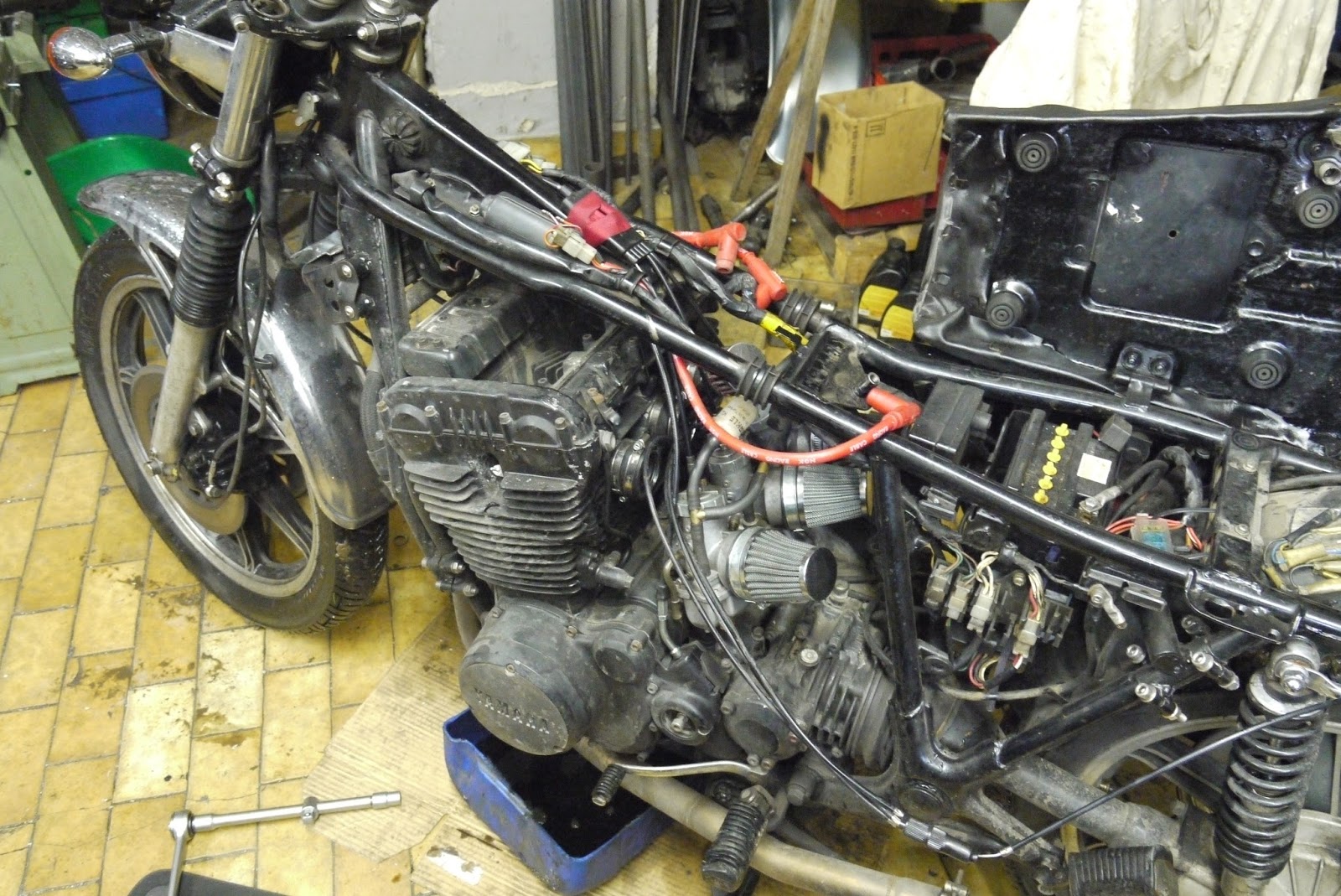

Remove the valve cover and here you can instantly see, why doing the headgasket is such an annoying job on a XS Triple, because you have to split the camchain to get the head off. This is actually quite the annoying show stopper and it took me about two weeks to buy just the link alone and not be forced to buy a completely new camchain. Even though in hindsight, that may or may not have been the worst idea, while I was at it.


Turn the engine over until TDC on cylinder #1.


Secure the camchain with some wire (old coathangers in this case) and choose the most unsuspecting link and split it!


Once that is done, the rest is pretty much as with any other DOHC inline engine, except for the fact that the cylinder of those XS Triples is really incredibly light!


Hard to see in the picture, but the headgasket blew out on cylinder #3 and especially around the oil-galleries on the far right. That being said, as the cylinder isn't anchored to the block at all, once you lift off the head, be prepared to do the base gasket as well.


As the studs are exposed to the elements, be prepared for the cylinder to become stuck quite easily and have a vacuum cleaner handy.


As my dad was helping me and the bores had already become slightly glazed, I present to you: My dad's first hone job. Not too bad, if I may say so and it definitely broke the edges on some of the rust spots inside the engine, so it was well worth trying it.


With the weird angle spark plugs are sitting at on an XS Triple, it won't come as a surprise that the threads are often a bit chewed up. A regular M14x1.25 tap and a bit of oil will take care of that permanently. Or until someone tries to get that spark plug in at an angle...


There's no such thing as too clean, when it comes to mating surfaces in my book. But especially with headgaskets, always make sure, the head and cylinder have a light cross-hatch to them.


Especially when reinstalling parts, make sure, you don't lose the cam chain in that tunnel...


No matter what, the shim buckets will come out. If you put them in a tray and mark their positions, it also rather easy (and a good opportunity) to note down all the shim-sizes installed and be totally prepared for when you have to adjust the valves.


Now setting up the valves is explained in an extremely complicated way in the manual, both the official Yamaha one and the book of lies. Basically what you want to do is put the cams in, with the markings facing up and then try to find the next position where the no lobe is pushing down on a valve. Once installed you use the hex which is ground onto the cams to adjust them back to the correct position with both dots pointing upwards and aligned with the lines on the camcaps.
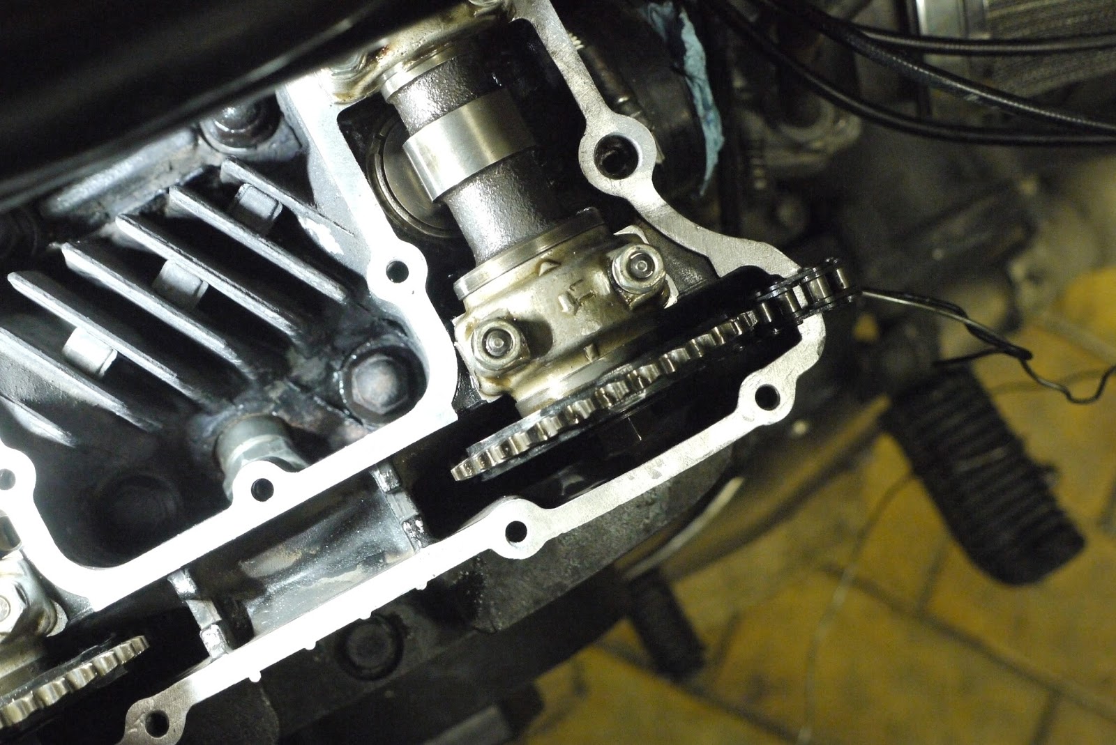


Assuming that you have your cams adjusted correctly and ready to rivet, stuff the openings where the camchain comes up full with paper towels or clean rags, so the camchain can't disappear and then insert (but don't rivet) the link.


Once you apply pressure through the camchain-tensioner opening in the cylinder block you'll realize, that the cam shifted a bit. Now the trick in this particular case is to make sure that the front part of the camchain on the exhaust cam sprocket is well loaded and then re-aligned with the markings. Then you set the inlet cam correctly and if everything lines up, rivet the link and mentally tick that box off.


Now among my worst ideas was to change the middle-gearbox and final-drive oil at the current temperatures. It actually came out pretty well, especially after flushing both out with copious amounts of diesel.


That 80W90 gearbox oil on the other hands is roughly as thin as some well-aged honey.


No idea what some people thought, when they were working on this the last time, but paper-thin ally washers may seal sufficiently once, but beefy,freshly annealed copper washers, now that's an entirely different story.


Last up was a quick drop of the carb needle on my VM36s. In order to not be forced to re-sync the carbs, I marked the position on both the carb body and the cap with some felt pen. The following pictures of the carb-slide on the other hand show you, why it might be clever to buy some aftermarket VM36s, because apparently Mikuni was willing to install really weird looking slides on these snowmobile versions.


And all of the above finally led to this:


There she is back out in the sunshine and let's just put it this way: She's grumpier than an East German weight-lifter before she had her "vitamins" and morning shave...


What you've just read, was two and a half days of work with massive support from my dad and some so far very rewarding results, as I found out that the cam-timing before was slightly messed up (intake cam retarded), which together with the blown headgasket was at least partly to blame for the somewhat mediocre overall performance before.

Wednesday, 6 December 2017

The new TR1 motor - Getting the rotor off (part 12)

Now this is one of the jobs dreaded by most, when in fact it's not that bad, in case you're using the correct tools for the job. The most important one being a hub puller.

The three bolts are m8x80 bolts (but the length depends on the puller used). It is of utmost importance, that you leave the nut on the end of the crank and only loosen it by three or four turns.  Otherwise you risk mushrooming the end of the crank or shattering it completely.


On the back of the rotor is the primary drive sprocked for the rear cylinder and the sprocket of the oilpump, which will remain on the crank after you pulled the rotor off.


Normally you don't have to heat the center of the rotor, but if someone overtightened it in the past or used some loctite or the wrong woodruff key... (The list goes on, you wouldn't believe the things I've seen in the past!) Then you can help yourself with either a proper oxy-acetylene torch or a silver soldering torch and heat up the taper on the opposite side of where the slot is. (That's the spot where it exercises the strongest clamping force on the taper.) Use the smallest possible nozzle you can and as hot as it will go. Tighten the puller and be prepared that it will literally "jump" off the crank that way.


There's six springs with six pins on the back. Dare to guess, why I am telling you this? 😉


And that's the left side without a rotor installed, as you will see, it really is possible to remove the oilpump with the rotor in place. When re-assembling I'll also show you, why I put the primary drive sprocket onto the rotor and then install and not the way round the Yamaha manual tells you to. 


All looking pretty tidy in there. So it's well about time to get those cylinders off and then take the cases apart. I can almost smell performance now. (Nope, that's just the scent of hot oil in the workshop from heating up the bearing!)


Sunday, 3 December 2017

The new TR1 motor - installing conrods (part 11)

With the crank-roller bearing and oil-pump-gear installed, it is well about time, to focus on the other important parts of the crankshaft, which are the conrods.

One of the benefits of plain-bearing crankshafts is, that if supplied with sufficient oil they are very, very durable. Nevertheless, once you're pairing cranks and conrods that haven't been together before, it is advisable to measure, check and double check whatever you plan to do.

As such I was forced to fit new bearing shells to my conrods. (How to take the measurements with plastigage can be seen in one of the previous posts.) The ones installed here are of the colour-code "black" size, which is the second tightest size and all in all quite a good guess, when you're swapping bearing shells on used XV-engines.


The crank-pin has to be cleaned meticolously. Spotless, won't do.


In absence of genuine assembly lube a high-molybdenium grease can be used as a substitute to prevent the contact of the bearing shells to the crank-pin until oil-pressure has been built up for the very first time. 


It looks a lot more than it is, just a gentle smear is plenty enough. 


The crankshaft is clamped into the vice (with some soft aluminium sheet to prevent the jaws from marking the crankshaft) and the rod-bolts are torqued to 48NM. 


One of the checks you should always do on engines is to check the rods for straightness and equal length. Factory stuff is usually pretty good, but aftermarket rods can be... interesting. The gudgeon pin should go through both rods smoothly, but without any play and the rods mustn't bind when rotating on the crank.  Additionally the gap (or absence of one to be more precise) should be the same both top and bottom.


With the crank now ready for installation into the cases, it is advisable to have a look inside the engine-case.

Wednesday, 29 November 2017

The new TR1 motor - overhauling an XV1100 crank (part 10)

With the engine cases being pretty well prepared, it was about time to build a decent crank for the new engine. To be fair, it went a lot smoother than anticipated. Probably mostly because it was dead cold that day.

As a start, I clamped the XV1100 crankshaft into the vice (but using soft jaws - some old ally strips).


Then I decided that I needed a tool to drive on the bearing onto the crank, which was a bit of 50mm stainless tube, beefed up with some off-cut to give it a bit more wall-thickness. 


On the other side, I welded on a big washer to give it a bit more rigidity.


Now while I was doing all of this, I've put a pot with a bit of fresh engine oil on a hotplate and heated it up until it started to bubble.


You won't believe the next step: Took the bearing out of the oil, held it with a rag and my thick welding gloves and simply pushed it onto the crank just with normal finger pressure. That's it, no fancy tools, nothing.


The oil-pump gear fought me all the way, for a some reason (stupidity, I guess), I washed it off with brake clean after heating it up in oil, which cooled it down too far (and the crank had heated up quite a bit with that big hot bearing sitting on there), which meant I had to build a second tool, following the same principle as above, but with 40mm inner diameter and then push it home using some spacers I had still lying around.


So that's the crank ready for installation. Conrods are next. 😏

Sunday, 26 November 2017

The new TR1 motor - installing an oil-pressure switch (part 9)

As I was waiting today for someone to visit me in my shop, I took the chance and finally drilled and tapped the cases in M10x1.0 for a standard VW 0.9Bar opener oil-pressure switch. Nothing fancy really, just make sure you drill straight into the case. Other than that...

Pre-drilled 6mm.

With a drill guide


Drilled it out to 9mm.


Tapped it and installed the sender.


Next step will be to take off the engine covers, remove the rotor and the cylinders/heads and then get into the meat of it and make some decent progress (finally).