The old Stinkerle is progressing very slowly, but it is progressing nonetheless. First step was to fit a rear tyre and also assess the situation with the XT350 rearwheel that I swapped in.
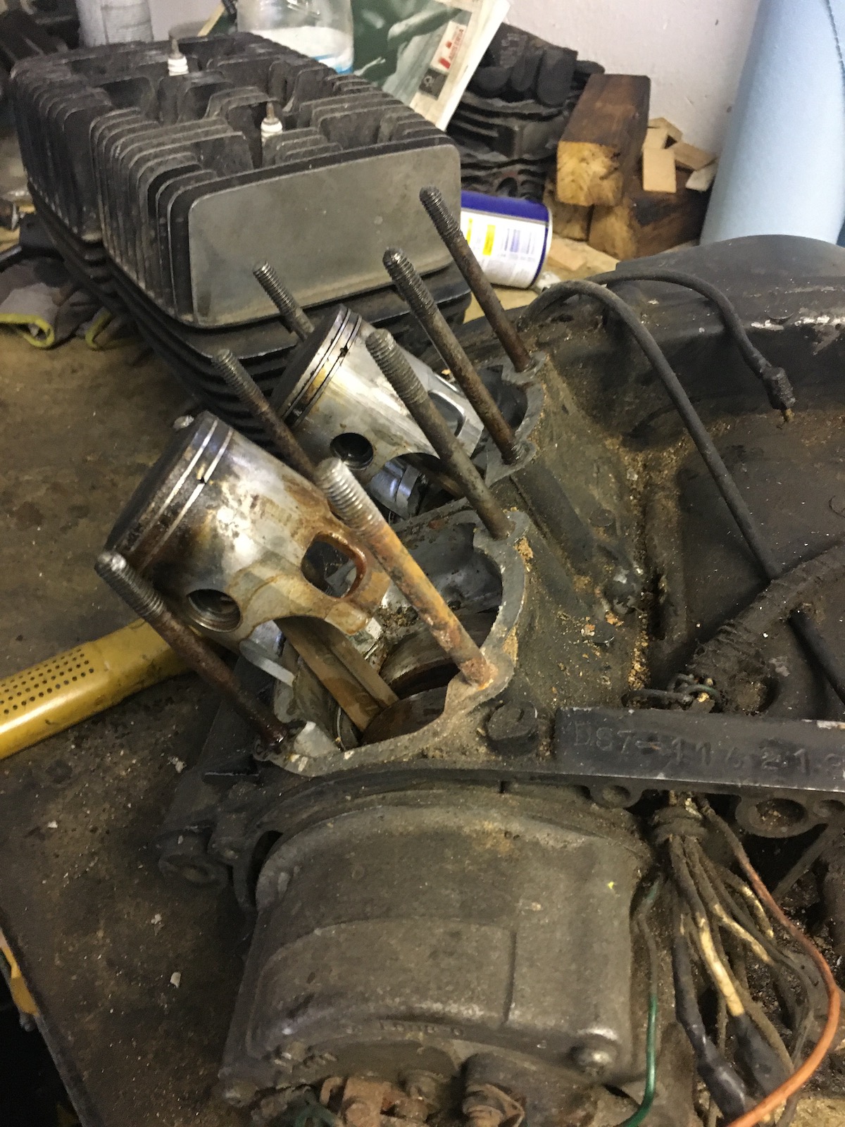
Fueled by this progress I decided to be brave and have a look at the bottom end of the engine. Because in an ideal world, a swap of the crankshaft seals should be sufficient to get the bottom end in working condition again and swap out the alternator and ignition setup for something a bit more suited for its future application, i.e. racing. (Especially as the completely misadjusted ignition was probably the case for the engine failure in the first place.)
In order to get the rotor off, a M10x1.25 bolt is needed. And compared to some similar setups on other bikes it was dead-easy.
On the other side under the clutch cover things looked even better. There was oil in there and the clutch looks like it hasn't done a lot of miles and there was nothing horribly wrong with it.
As the oil-pump will not be used again, the drive gear can be removed. (It's just a press-fit.)
The clutch basket was in good shape and I didn't lose the ball that sits between the pushrod and the pressure-mushroom.
Splitting the cases is pretty simple on old RDs, but this was when the first (and only) nasty surprise came up. As the Stinkerle is parked near the workshop door some rain must have gotten into the crank-case and made the crank start to rust.
My loss is your gain though, as this means, I'll do something I haven't done in ages: rebuild a two-stroke-crank. (But not today - I first need the bearings and I have to either borrow a press or build my own - let's be honest, expect a hydraulic press build soon!)
Lastly the black paint smeared on the cases looks remotely acceptable in the pictures, but in real life a bit of industrial grade paint stripper quickly dealt with the matter.
Just a little bit of cleaning up with a plastic brush later and the cases look good again!
So what are the next steps? I need a hydraulic press (wanted one for a long time anyway) and then have to rebuild the crank. Also I will check the bore-size on the cylinders and then have a look, what the next suitable oversize will be.
Ever since the days, when I did multiple RD engines for some other people, did I want to build a quick two-stroke for a bit of vintage road racing on a budget following the classic Colin Chapman mantra: "Simplify, then add lightness."
Over the last few years I have amassed quite a few left-overs from various other bikes. With the move completed it's now time to have a look at all the parts and decide whether the best course of action is to sell the whole lot and never speak of it again or actually dig into it and build a usable racebike from it.
The engine is the biggest unknown quantity, as all I knew about it was that it was stuck. Better start somewhere else then. 😉
For mere test-fitting the old ball-bearing headstock bearings would have been more than sufficient. But over the years not a single one of the balls stayed where it should, so new tapered roller bearings were the order of the day.
Equally shocking (and a good indicator to the troubled past of this frame): some had already installed a needle-bearing conversion in the swingarm and some grease fittings.
Moment of truth:
Yep, piston seized in bore (what I secretly hoped for) and not a seized crank. And both pistons were in a position, where they more or less close inlet and exhaust ports. The root cause most likely being a combination of the ignition timing being waaaay too advanced and still a relatively tight bore from the cylinders being freshly honed.
Even though someone in the past had already put on RD250 cylinders (this is a YDS7-block) and try his (or her) best to slaughter the engine, the crank still feels fine and rotates freely. It must have been dry and oily down there. So nothing but a good clean up and we should be golden.
Talking of cleaning... I chiseled and washed off about one to two kilograms of caked on dirt from the engine.
And yes, I went with the ubiquitous RD50 fuel tank. Just a note, it fits nicely on the frame, the petcock has to be moved a bit further forward to better clear a frame rail.
Not sure about the seat hump, it's what I have at the moment and it fits quite well over the frame rails.
So what's the bigger plan: I've ordered some super-cheap 125 expansion chambers, because I don't have any exhausts. I already have a set of mildly worn out RD250 cylinders, pistons and cylinder covers. A set of SR500 front stanchions should come in over the holidays and I already have all the bits for the rear wheel, which are missing in the pictures. The ultimate goal is to stay as close to the 100kg-mark as possible, which currently looks rather doable. Now if I can get the engine to make around 30-35hp with the given carb and exhaust setup this should be plenty enough for me.
Squishband (or -area) depending on the design of a cylinder head is the area were the fuel-air-mix is forcefully compressed more than in other areas with the aim of aiming the gas towards the spark plug in order to improve the speed and efficiency of combustion. Thus reducing the required amount of ignition advance.
Aircooled RD350 engine, late model electronic ignition
The first step in any modification of an engine is quite simply put the assessment of the current situation.
Take the head off and...
Wössner RD350 two-stroke piston - work of art
... be greeted by a wonderful new Wössner piston for RD350ies. (Lovely)
Modified RD350 cylinder head with a 12.5mm squishband
Unfortunately, I was also greeted by this. For the sake of fair play, I have to spill the beans and admit that this is the engine of a friend and I did the 250 to 350 conversion for him. Unfortunately, somebody had modified the cylinder heads in the past and not exactly the way this was going to be helpful for a mostly stock engine. The distance between piston crown and combustion chamber roof, was an enormous 2.2 and 2.35mm. And just if that weren't bad enough, there was a lip of the headgasket protruding into the combustion chamber just as the actual head was turned too small thus creating another hot spot.
Now the 2.2mm gap could quite well be intentional, as these heads could have been fitted to a race engine, which was running both without a basegasket and had the cylinder itself shortened by the height of the headgasket relieve. Yet this is not an excuse for machining the head too small and also for the headgasket.
Headgasket 1.35mm thick
I checked the relieve in the cylinder and it was 0.65mm on the left and 0.75mm on the right. So the given headgasket, which measured a whopping 1.35mm thickness. This was to be added to the already enormous gap, bringing the "squishband" almost 3mm away from the piston crown. Way too much. A good figure for a RD350 engine would be 0.75 to 0.8mm so that the squishband is most effective, yet still leaving a bit of room for conrod stretch and a bit of play in both the big-end- and small-end bearings.
A stock RD350 head and combustion chamber (for comparison)
Conservative 60ies and 70ies desing demanded around 50% of the combustion chamber surface to be used as squish-area. Modern designs lower this figure to around the 30% mark, which in this particular case would have been a ring around 10mm wide. As the squishband is meant to accelerate the charge towards the spark plug it should, quite logically, be angled.
Now here are two schools of thought. If you machine a very steep angle into the head (as seen in the picture above) the mixture will travel to the spark plug without being compressed overly much. It will do so, but not in a very fast way (still heaps faster than stock, but you get the idea!) Now if you used a very shallow angle, let's say around the 3 to 5 degree mark, the charge would be pre-compressed, heated up and would burn a lot faster, because it has already picked up a lot more speed.
There's many ways to actually measure the distance from piston crown to the roof depending on the size of the gap. In this particular case the distance was too big to use solder or twisted strands of solder, so I had to resort to some sort of clay in order to get the cylinder heads in the right ball-park to start with.
In order to make your actual measurement, the engine has to be reassembled, in this case meaning that the heads had to reinstalled and torqued to spec. (20Nm) Then the engine is turned over until the clay hits the cylinder head, everything is removed and the crank is turned until it reaches TDC. Now the height of the protruding clay is measured as this defines the amount of material to be removed from the head.
The cylinder head is installed on the lathe adapter in order to be machined.
As I am using an almost seventy year old lathe, DRO's are a no-go. So I had to restort to an ARO (analogue readout, aka. a dial-indicator) in order to only take off the required 1.1mm on the left and 1.2mm on the right cylinder.
As it turned out after a few revolutions, not only was the cylinder's squishband machined too wide, the cylinder head had also been tilted somewhat during the operation and as such wasn't perfectly perpendicular to the piston crown and sparkplug.
These two videos are meant to give a slight impression, why this was actually a quite time consuming process. As carbide inserts were used, the feeds and RPMs had to be a balance between very modest feeds (0.1mm feed) and a relatively wavy surface finish and the imbalance caused by the off-center sparkplug thus inducing quite a bit of vibration. The speeds shown are the slowest and second slowest backgear speeds.
Last order of the day was to cc the actual combustion chamber by filling a graduated vessel with water. (In this case to the 600ml-mark.) The next step was to form a clay mould of the combustion chamber and then drop this in the bowl and measure the extra milliletres with a syringe, which came out at a spot-on perfect 30cc.
The nice thing about two-strokes: very few moving parts and lots of tuning potential. The downside: Lots of things going wrong. One of the most pivotal points in making reliable power in any internalt combustion engine is the correct amount of squish.
In order to rectify the squishband width and height on two aircooled RD350 heads, I had to knock up this little tool.
Now you may (quite rightfully) point out, that this tool seems a bit excessively complicated, with all the lathe work and welding, but (and that's a big one) one of my lathe gears has spit out two teeth in the past and so I can't cut threads on the lathe...
But let's start at the beginning. Let's start with one sparkplug minus it's ceramic insulator.
Next was to turn a shaft on the lathe that is a light press-fit in the sparkplug.
Chamfer the lip of the old sparkplug to make pressing the shaft in a bit more easy.
E Presto:
After welding it up (see first pic) it had to be trued up again...
Runout is absolutely brilliant (0.1mm 50mm away from the chuck)
Do some cosmetics to it and file in two flat spots so it can be undone with a 17mm wrench
And test fitted a head in the lathe - job's a good un'