

If you compare the two boxes in the picture below (672 on the left, 671 on the right), you can see that they are pretty much identical, even though the traces are drawn slightly differently and the components are sometimes positioned differently, e.g. at the bottom three caps instead of four are used and the tantalums are after instead of before.

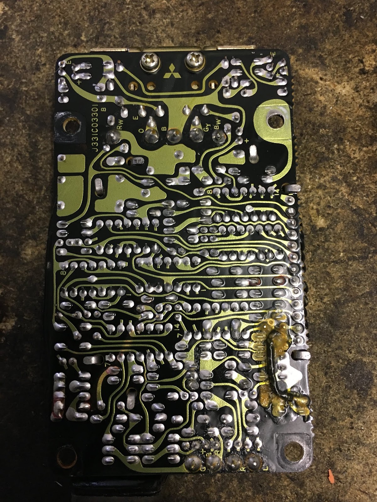
It's a bit hard to see in the picture above, I but I suspect that at least part of the problem are the solder joints, which probably due to a combination of heat-cycles and vibrations have started to become corroded.

Also interesting: Obviously an in-production fix with a bit of black wire.
Anyway the task for the day was to split the boards and then tackle the coating.

I found the best way of attack was to submerge the board in Acetone for 1-2hrs, even though this isn't without it's own problems: If you scub too hard, you can quite easily scrub off the print from the chips and also the plastic wrap on the caps will get soft and come off. (So expect to measure at least some of the caps by hand as the labels have fallen off.) The picture shows the goo after about 45 minutes in the solvent. I poked it with a pick to make sure the acetone would get between the pcb and the goo securely.

To pluck the coating off, I think it was best by letting it dry a bit afterwards as the coating wouldn't really stick to the pcb anymore and become a bit harder again, meaning I was able to get it off with some needle-nose pliers and a pick and lots of patience...

Strictly speaking just for soldering the cold joints, just a good scrub on the back of the boards would have been sufficient, but in order to work deeper into the box, removing all the gunk was definitely worth it.

And as you can see, a lot has come off already.

Next step will be to check the transistors and all the caps in order to find out, whether there's anything wrong with them or whether it was really all just down to those "weeping" solder joints as seen at the beginning of this post.
No comments:
Post a Comment