Showing posts with label DIY. Show all posts

Sunday, 9 January 2022

The SR500 sidecar - finishing the sidecar mounts (part 10)

First things first, last time when I returned the next day after the little Zinc-plating session, I was shocked to find some very rusty parts in my shop.

A quick rubbing with some scotchbrite solved the situation and another go in the bath (much longer this time) made sure it hasn't happened again since then. 

After this shock I started with the first and most simple mount on the bike as far as the clamps are concerned, the rear upper mount. Unlike on my last SR-sidecar I wanted to retain the inner rear mudguard as it keeps a lot more dirt away from the engine than one would think.


And with that out of the way, it was time to turn towards the front lower sidecar mounts. Marked the parts on the lathe and then drilled and milled them. As I had decided to go with 12mm thickness one of the struts was used as my thickness gauge. 


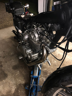
The downside of my beefier front mounts is the fact that I have jack up the engine to get the inner mounts between frame and engine. Once in, everything clears nicely, even though I had to shorten the left-side stud a bit as it was touching the engine, once tightened.
Now the bit between those two clamps was meant to be a very simple case of some 30mm stainless bar that I had over from some other work. Turns out my 10.5mm drill decided to call it a day on the second hole and wallowed said hole out to 11.xx mm. No chance of drilling a half usable M12-thread in there. Lobed the other end of (and got a few new drills the next day) and made two spacers with M12 threads in the middle and grabbed some 20mm stainless bar from the shelf.

With a little recess machined into the back they were a breeze to TIG onto the 20mm bar.

There you go, looks overly complicated, but works just fine - front top mount is more of the same.

Ball-head was straight forward and that knife-head really works nicely, if you put on some fresh inserts...
 

And then it's spot all 4 mounting points on my SR500.

At this point it could be all so simple: shorten the struts, alter the lower front sidecar mount so it can connect to ball joint and weld on a block for the rear swivel mount. Easy three or four hours of work (it's the small stuff that takes time), put the wheel on the axle and be the coolest kid in the neighborhood.


I swear I had the best intentions to leave the sidecar-chassis alone. Really.

Tuesday, 28 December 2021

The SR500 sidecar - electroplating for rust-protection (part 9)

 ... because to be quite honest, I somewhat failed in the "looks"-department. The setup is fairly straight-forward: a power-supply, zinc-plate/-anodes, some white vinegar and salt and some blue-chroming solution.

But I'll be honest straight away, I didn't make my own zinc-solution as I couldn't get my hands on sufficiently undiluted white vinegar. (40 percent essence would have been the ticket.)

The process is fairly simple. All the parts have to be clean and I don't mean clean, but eat your dinner of them clean. All traces of grease, oil, etc. have to be removed, which I did by dipping them in acetone for a good few minutes. (As the final parts show no fingerprints etc. that seems to have worked rather well.)

Next step is the actual Zinc-plating and it's equally straight forward: workpiece on negative (-) and your zinc-anode/roofing-sheet/drain-pipe on positive (+). The trick and that's where I suspect my somewhat sub-par results came from is to do it sufficiently slowly. 9V and around 5A is cool and gets a lot of Zinc into the solution, but you end up with rather furry workpieces. I suspect 6V and 1A (or maybe even less) is the ticket to a nice surface finish. Either way, if you see bubbles on your workpiece things are going the right way. On 5A 2 minutes were more or less sufficient to uniformly coat it black/dark grey.


Watching the Zinc "creep" over the workpiece is very cool to watch.

After about a minute the distribution is still rather uneven.


The part where you can't cheat as easily and shouldn't make the solution yourself, because of potentially cancerous Chromium-compounds in gaseous form, is the blue-chroming solution. It's very straight forward to be honest. Just dip the part and watch the results.

For a full blown silver(-ish) Chrome layer to be deposited the parts have to reside in the solution for about two minutes.

Obviously in the cold it needs a bit more than that. I'll add the results to this post, once I've had the parts in a bit longer. Technically it's probably alright with the Zinc-layer on the thick side, but as at least some of the mounts will be rather well visible on the sidecar, a bit of vanity shall be allowed this time.

Sunday, 7 November 2021

The SR500 sidecar build - A boat (part 5)

... a boat, a kingdom for a boat.Well not quite a kingdom, more like some resin and some glassfibre matts. Guess there's a first time for everything and this time it was making a mess with glassfibre and polyester-resin. Why polyester and not 2k? My lack of knowledge and I have always been told that these Velorex sidecars are made from polyester, so I was pretty convinced that sticking with the same stuff would be the right choice.


So here's what I learned: Respirators aren't dumb, I worked in my dad's garage with both doors open and a gentle breeze going through and I ended up with a proper headache, so the whole "well ventilated area"-thing is no joke and honestly even two weeks later the resin gave off a very distinct smell. The next thing is: plan ahead. I cut up a fair amount of strips and patches beforehand and but them in the old oven tray for later use. (Also the mat is the cheap part, so saving there will not change much, but make the whole affair a lot easier.) On the subject of mats, there's coarse woven ones, fine woven ones and those "messy" ones. I picked up a pack of each as I saw that the boat was covered on the inside with the erratic stuff and the substructure was made from the coarsely woven stuff. 

Another tip on personal protection, remember the pink (or in my case yellow) kitchen gloves your mum or granny used, when doing the washing up? Yep, get a pair of those and then wear a pair of normal nitrile gloves over them. This way you end up with NO glasfibres on or in your skin and you can take off the second pair of gloves, when you have to cut some additional bits of mat and don't have to bother with sticky resin being everywhere.

Whilst I was picking up some supplies, I also got some paper cups for mixing and picked up this little tray, which appears to have been some sort of cheese wrapper or the like. If you can get one of those bigger trays, like the ones in which meat is sold in, you'll probably have an even easier life. 

Originally I anticipated the resin to be much thinner than it actually was, yet still it surely didn't do harm to put the boat onto one side to have gravity work in my favour. The work itself is pretty simple: You put the bit of mat you want to use into the tray, pour some resin on top of it, mash it in with a brush until it is a sticky mess and then take it out and place it on the hole you want to patch up. As there will be quite a few air bubbles trapped underneath tap it flat with a brush.


I then waited about a week or so (more like ten days to two weeks), cut up some of that messy mat, soaked it will and dear with resin and filled up the hole from the outside. 


As the reinforcing lips on the sidecar body had quite a few cracks, I made some strips and laid them over the cracks inside and out. It looks terrible in the picture, but the excess material can be trimmed back later when the resin has hardened.

And there you have it... that's all I know after working with GRP for a couple of hours. 😁

Saturday, 16 March 2019

The next version of the Mk.7 exhaust

This is the third revision of my Mk.7 exhaust design, effectively making it Mk.7.3. Now the original Mk.7 prototype served me very well over the last or maybe even the last two seasons, but despite my best intentions, when building it, it still left some to be desired. First, I knew I could improve on the build quality thanks to a new welder. Second, I knew I could improve on the fit and finish thanks mostly to a much improved welding table, which actually kept the parts flat during welding. And then there was the issue of the old downpipe on the left touching the chain tube and melting it.

So when setting everything up, the clearance between pipe and chain gaitor was deemed essential. (That's about 10-15mm, measured at max. swing of the swingarm.)


But starting from the front, in this case the cylinder head, I wanted to have nice, meaty flanges and location rings to center the downpipes in the port and ensure good seal, as they wouldn't warp easily. I also turned a step into the rings to make it easier to weld them onto the pipe.


A great deal of time was spent on making these two collectors and unlike in previous versions making sure that all the sleeves are pointing the right way in order to prevent leakages.


As I had started from the silencers towards the collectors, the next logical step was to work back from the front in direction of the collector.


Because the tubes had lots of bending marks, a bit of polishing was due. The thing with polishing is though, once you start with polishing at one end, you have to do the whole lot or it'll look a bit odd.


With the two Y-pieces of the collector already being built, the actual collector almost built itself as it was more a pretty simple case of connecting the dots.


The last part that I had to build was the rear downpipe, going to the collector. Building it imposed two main challenges: 1) clear everything, go through the frame and allow suspension movement and 2) be of as close as possible of the same length as the front downpipe. Which if you have a careful look at the bike is quite the challenge in its own right. Suffice to say, making the rear downpipe almost took as long as all the remaining parts.

This is the go-through-the-frame-without-touching-anything-part.


And once it has come out of the frame it "just" had to clear the collector and other pipework and meet up with the sleeve.


If you look very closely at the last picture, you will notice a section, which in reality is about 25 to 30mm long which looks a lot like an afterthought. This was the hardest part to fit on the whole exhaust as it had to compensate for the total sum of all misalignments of all previous cuts.

The last step was to weld in a bung for an O2-sensor (even though I currently do not have any intentions of using one) into the main bend of the collector. The angles and positioning of these are rather sensitive, e.g. the nozzle of the sensor has to point downwards to prevent it from collecting moisture and it also has to be as close as possible (but at least 50cm from the exhaust valve) and there's should be no exhaust leaks ahead of it. If you want to follow all of these requirements, you aren't really left with too many positions to put it and as I didn't want to install two sensors, there was really only one position left.


And then it was ultimately the last time to take the exhaust apart and polish up all the parts.


And this is the final result (admittedly the silencers aren't done yet).


To be fair, there's been a lot of mishaps, as originally this was meant as a completely new generation of my exhausts, I had to redo the sealant on the cylinder foot, when swapping valve springs. Oh and then there was this little episode, where I woke up, because I was absolutely certain that I had mixed up the valve timing on the rear cylinder ...