Friday, 21 January 2022

The SR500 sidecar - absolutely not modifying a Velorex 562 frame (part 11)

 ... I mean it would be the sensible thing to do to pretty much do nothing at all. Would. Have. Been. On the other hand stock mounts are 29mm tubing and relatively thin-walled too. (We're talking about 2.5mm wall thickness before it got attacked by rust. There's quite a few tales of snapped lower front mounts on Velorex'es actually.)And on the other hand, there was this absolutely gorgeous 30x5mm thick wall seamless tubing sitting on my bench. 

... the sort of rust one finds on a tube that was sealed off properly. Doesn't take much imagination to work out what one of the more exposed tubes might look like on the inside.

Modify the new thick wall tube for clamping ...
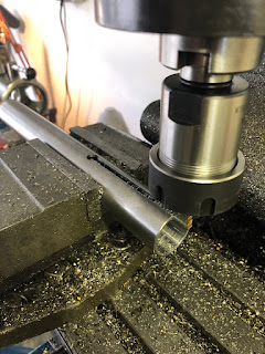
 and then weld it in.

And the same on the rear. (If you tell me, starting with an IZH Sputnik sidecar frame would have saved me from a fair bit of work... yes, it's essentially what I copied and yes, it would have been cheaper as well.)

Bit of bracing in the corners and as mounting points for the upper struts.


And with those welded on it was well about time to decide on the geometry of the sidecar, draw it up on the floor and then make the swan necks. Lead was decided to be 265mm and the track width 1080mm.


Strictly speaking, at this point it's a sidecar.

Obviously the rear strut is "a tad" long. Now the simple way would be to just throw it on the bandsaw and weld it back somewhere in the middle. (See the soon to be replaced front strut.) Now there's two problems with that: First you shouldn't load a weld with bending forces or if that's not an option, at least put a reinforcing tube on the inside. In the case of these struts said tube would get into serious conflict with threaded adjuster. There is a right way though. In original form, there's a pin which slides into the tube, so if one has to shorten one of these, start at the base and free the pinned end.

Also due to the beefyness of the pin, cranking the welder up to 11 is an option.

And there you go...

... or do you? I had to make one more set of top hats, so the flange bolts would only be loaded under tension and not on bending. (Same idea as above.)

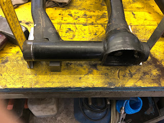
At this point I realised that my sidecar sits about 40-45mm too high and the sidecar swingarm needs to be modified. With the stock Velorex shock being questionable and unreliable at the best of times, the next step will be to make a new sidecar swingarm, which will then incorporate a regular length SR500 rear shock. This will give me more suspension travel and due to the different shock angle also a stiffer suspension. Oh and those extra 40mm should also allow me to fit the 18inch sidecar wheel within the stock mudguard without trimming off the lip like on the last one.

Sunday, 9 January 2022

The SR500 sidecar - finishing the sidecar mounts (part 10)

First things first, last time when I returned the next day after the little Zinc-plating session, I was shocked to find some very rusty parts in my shop.

A quick rubbing with some scotchbrite solved the situation and another go in the bath (much longer this time) made sure it hasn't happened again since then. 

After this shock I started with the first and most simple mount on the bike as far as the clamps are concerned, the rear upper mount. Unlike on my last SR-sidecar I wanted to retain the inner rear mudguard as it keeps a lot more dirt away from the engine than one would think.


And with that out of the way, it was time to turn towards the front lower sidecar mounts. Marked the parts on the lathe and then drilled and milled them. As I had decided to go with 12mm thickness one of the struts was used as my thickness gauge. 


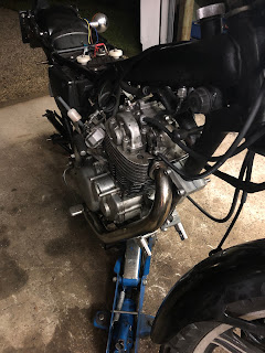
The downside of my beefier front mounts is the fact that I have jack up the engine to get the inner mounts between frame and engine. Once in, everything clears nicely, even though I had to shorten the left-side stud a bit as it was touching the engine, once tightened.

Now the bit between those two clamps was meant to be a very simple case of some 30mm stainless bar that I had over from some other work. Turns out my 10.5mm drill decided to call it a day on the second hole and wallowed said hole out to 11.xx mm. No chance of drilling a half usable M12-thread in there. Lobed the other end of (and got a few new drills the next day) and made two spacers with M12 threads in the middle and grabbed some 20mm stainless bar from the shelf.

With a little recess machined into the back they were a breeze to TIG onto the 20mm bar.

There you go, looks overly complicated, but works just fine - front top mount is more of the same.

Ball-head was straight forward and that knife-head really works nicely, if you put on some fresh inserts...
 

And then it's spot all 4 mounting points on my SR500.

At this point it could be all so simple: shorten the struts, alter the lower front sidecar mount so it can connect to ball joint and weld on a block for the rear swivel mount. Easy three or four hours of work (it's the small stuff that takes time), put the wheel on the axle and be the coolest kid in the neighborhood.


I swear I had the best intentions to leave the sidecar-chassis alone. Really.

Tuesday, 28 December 2021

The SR500 sidecar - electroplating for rust-protection (part 9)

 ... because to be quite honest, I somewhat failed in the "looks"-department. The setup is fairly straight-forward: a power-supply, zinc-plate/-anodes, some white vinegar and salt and some blue-chroming solution.

But I'll be honest straight away, I didn't make my own zinc-solution as I couldn't get my hands on sufficiently undiluted white vinegar. (40 percent essence would have been the ticket.)

The process is fairly simple. All the parts have to be clean and I don't mean clean, but eat your dinner of them clean. All traces of grease, oil, etc. have to be removed, which I did by dipping them in acetone for a good few minutes. (As the final parts show no fingerprints etc. that seems to have worked rather well.)

Next step is the actual Zinc-plating and it's equally straight forward: workpiece on negative (-) and your zinc-anode/roofing-sheet/drain-pipe on positive (+). The trick and that's where I suspect my somewhat sub-par results came from is to do it sufficiently slowly. 9V and around 5A is cool and gets a lot of Zinc into the solution, but you end up with rather furry workpieces. I suspect 6V and 1A (or maybe even less) is the ticket to a nice surface finish. Either way, if you see bubbles on your workpiece things are going the right way. On 5A 2 minutes were more or less sufficient to uniformly coat it black/dark grey.


Watching the Zinc "creep" over the workpiece is very cool to watch.

After about a minute the distribution is still rather uneven.


The part where you can't cheat as easily and shouldn't make the solution yourself, because of potentially cancerous Chromium-compounds in gaseous form, is the blue-chroming solution. It's very straight forward to be honest. Just dip the part and watch the results.

For a full blown silver(-ish) Chrome layer to be deposited the parts have to reside in the solution for about two minutes.

Obviously in the cold it needs a bit more than that. I'll add the results to this post, once I've had the parts in a bit longer. Technically it's probably alright with the Zinc-layer on the thick side, but as at least some of the mounts will be rather well visible on the sidecar, a bit of vanity shall be allowed this time.

Tuesday, 21 December 2021

The SR500 sidecar - finishing the mounting blocks (part 8)

Last time I wrote about the sidecar mounts, I was pretty convinced that they are more or less done. Yup, when going through that last post on sidecar mounts (part 6), I had a good chuckle myself. 
First order of business - make the parts look a bit better and chamfer them. Technically completely superfluous, but visually appealing. (And if that's the sort of eye-candy needed to convince the engineer that those are some well made clamps - which they are - then heck, let's do it.)


As I decided that I would never again fit the bash plate anyway and it would allow me to mount the lower mounts a bit higher up, the tabs for the afore mentioned guard had a date with Mr. angle grinder. 

As my sidecar mounts are (intentionally) a bit beefier than the original clamps that originally were on my first SR500 sidecar, the engine had to be unbolted and lifted up a bit in the frame to squeeze the mounts in.

To be honest that wasn't enough and 3mm had to come off of the back side of the clamps. A 50mm knife head makes short work of that.

When fitting the mounts I remember a little detail that annoyed me on the last SR500 sidecar conversion:  The two outer bolts are easy to reach and tightening the nuts is no problem, but the two inner ones...

... as such I threaded the clamps for M12-bolts and now can comfortably tighten them from the front.

Squeezing the rear mount in between airbox and frame required the same mods aside from me having to cut out the splash guard.


The astute amongst the blog readers will have notice the absence of the top mount with its puny M6 bolts holding the two halves together. Well that's currently sitting on the mill getting drilled out to M10, after being dramatically slimmed down as it looked both disproportionate with no particular gains in terms of stability.


 The big lesson learned here was - high quality wood routing bits are awesome for chamfering (or rounding corners, if you buy the right bit) and it's not the end until you're done. Also... can I weigh in swarf? The last picture gives a good indication what my workshop floor looks like at the moment.


Saturday, 4 December 2021

The XS Triple Sidecar - XS1100 swingarm installation

It all started with a comment from Ralf that he fitted an XS1100 swingarm and final drive into his XS750 sidecar. To be fair I had the same idea a while ago, but it always only came back to mind, when I really needed the old girl to be working and doing her thing on a daily basis. 

The hard facts: approx. 7 percent shorter gearing, which should fix the issue with a slightly long first gear, when pulling a sidecar and as an added bonus 30mm more wheelbase due to a longer swingarm and being quite a bit sturdier than wouldn't do harm either. 

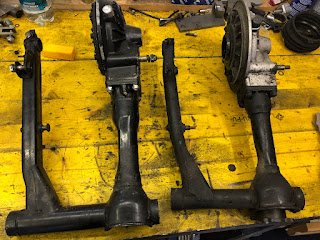
It's rather apparent that not only the XS1100 swingarm (on the left) is beefier than its 750 counterpart, but also quite a bit wider.

19mm wider to be precise. Luckily due to the way the swingarm mountin is arranged on these bikes the odd millimeter up or down wouldn't make a differents as the swingarm runs on adjustable pins.

With the in mind, only way to do this - get the angle grinder out and hack that swingarm to bits. Sounds dramatic, but I knew that the outer bearing cup was originally only welded on (for those who want to do the same, the lip is about 5mm deep), so cutting it off sufficiently far away from the cup made the rest a rather simple job.


Clocking it up in the lathe using the original bearing cup of the swingarm bearing as a reference was a tad nerve wrecking, but I got it within 0.02mm between high and low spots.

Then turned it down to a nice press fit inside the swingarm tube

A final sanity check with the cup pressed in and it ended up spot on in terms of the width. Same 281mm as my stock swingarm.

An old 17mm rear axle out of a XV750 had to sacrifice it's thickened part, where it normally is clamped in the swingarm to act as a draw bar and alignment tool for the swingarm. 


I admit, my TIG weld looks nicer than the stock MIG weld that was there before. It's probably also a lot stronger. (There were some penetration issues in the original weld that became apparent, when I shortened the swingarm.)

Fitting the swingarm was a royal pain as it is rather heavy and obviously imbalanced and there's not a huge deal of room to wiggle it in. Also some idiot forgot to put the rubber boot on.

Swingarm out again - aside from the width, the indent on the right and the brake brace mounting point had to be modified.

Next stop was the splash guard on the rear wheel. Turns out with it installed the rear wheel doesn't clear the final drive housing.

The bolts dig into the housing and if you were to replace them with countersunk bolts the studs of the final drive housing eat into the shroud.

Once you look at both the triple and the 1100 units, it becomes rather apparent why it won't work as the 1100 unit is more or less flat and the triple inner cover has got the wheel coupling sitting a notable bit further out, giving plenty of room for the shroud.

In the end it all aligned rather nicely.


Let's waste no more time and tackle the elephant in the room: Was it worth it? Oh hell yeah. First gear is now short enough that I can take off without touching the throttle on level ground. First and second gear as soon as the engine gets into the power band makes the rear wheel light up and me grin like an idiot. And in the end, ain't that what it's all about?