Saturday 25 January 2020

XV Ignition Intermission - parts list for metal box ignitions (pt.4)

I am not going to say this is the moment you all have been waiting for, but I have a (for now) preliminary parts list of the J4T00671 and J4T00672 boxes. I haven't had the time to check the caps on a second box, hence this being preliminary information for now.


As you can see, the board is only populated on one side. Both the ceramic and epoxy caps have not been checked by me and I only went with what was printed on them. In reality most likely only the electrolytic caps will be relevant for swapping anyway, if you're really unlucky then a transistor might have gone south as well. But after having chatted with some other people, who tried their luck in fixing these, resoldering (obviously) wonky solder joints has done the trick for them.

Main Transistors (2)
2 x 1D1 ETD51-030 -> substitute BU941ZT

Logic ICs (10)
3x TC4001BP (NAND Gate, 4 gates, 2 input, 1 output)
3x TC4011BP (NOR Gate, 4 gates, 2 input, 1 output)
4x UPC451C (Quad-op-amp)

Electrolytic Capacitors (12)

9 x 1.0μF 50v
2 x 0.22μF 50v
1 x 4.7μF 50v

Ceramic Capacitors (23)
8 x 10² (1000 pF)
5 x 10³ (10000pF)
7 x 223 (22000pF)
2 x 472K (4700pF)
1 x 473M (47000pF)

Epoxy Capacitors (6)
3 x 10⁴K (100000pF)
2 x 153K (15000pF)
1 x 10³k (10000pF)

The numbers in brackets are the total amount of components and are really just meant as a sanity check for me to make sure I've covered all of them. Should you find errors, please feel free to post a comment and I'll recheck and update this post.

Sunday 19 January 2020

XV Ignition Intermission - comparing both versions & preparing for work (pt.3)

As luck would have it, I found out that my Everyday TR1 originally came with the older J4T00671 ignition and as I had to solder in a separate wire for the tach-signal, both boxes were open and I could quickly compare them.


If you compare the two boxes in the picture below (672 on the left, 671 on the right), you can see that they are pretty much identical, even though the traces are drawn slightly differently and the components are sometimes positioned differently, e.g. at the bottom three caps instead of four are used and the tantalums are after instead of before.


It's a bit hard to see in the picture above, I but I suspect that at least part of the problem are the solder joints, which probably due to a combination of heat-cycles and vibrations have started to become corroded.


Also interesting: Obviously an in-production fix with a bit of black wire. 


Anyway the task for the day was to split the boards and then tackle the coating.


I found the best way of attack was to submerge the board in Acetone for 1-2hrs, even though this isn't without it's own problems: If you scub too hard, you can quite easily scrub off the print from the chips and also the plastic wrap on the caps will get soft and come off. (So expect to measure at least some of the caps by hand as the labels have fallen off.) The picture shows the goo after about 45 minutes in the solvent. I poked it with a pick to make sure the acetone would get between the pcb and the goo securely.


To pluck the coating off, I think it was best by letting it dry a bit afterwards as the coating wouldn't really stick to the pcb anymore and become a bit harder again, meaning I was able to get it off with some needle-nose pliers and a pick and lots of patience...


Strictly speaking just for soldering the cold joints, just a good scrub on the back of the boards would have been sufficient, but in order to work deeper into the box, removing all the gunk was definitely worth it. 


And as you can see, a lot has come off already. 


Next step will be to check the transistors and all the caps in order to find out, whether there's anything wrong with them or whether it was really all just down to those "weeping" solder joints as seen at the beginning of this post.

Saturday 18 January 2020

XV Ignition Intermission - getting the board out of the case (pt.2)

Now this may seem a bit trivial, but if you are the careful type like me, let me tell you one thing: The conformal coating has been applied rather liberally and as such even some things, which you wouldn't expect to stick together are actually sticking together, like the heatsink and the case.

The box the pictures have been take with, has never been opened and was (prior to me opening it up) in pristine condition.


When you flip it over, you will be able to see four tabs, which can be bent out of the way with a large flatblade screwdriver.


The cover-plate itself might be a bit sticky and may need a bit of prying and levering to be removed.


In order to remove the board from the case not only the four plainly visible screws have to be removed, but also the two, which hold the heatsink of the transistors to the case.


In my case the heatsink was stuck to case rather firmly with the conformal coating paint and a bit of prying with a thin screwdriver was unavoidable. 


The rubber, which guides the cables through was glued to the case as well.


And this is the empty shell you are left with in the end. Now in order to get the mother- and daughterboard apart, a few holding tabs have to be straightened out.


After trying it both ways, it seems to be better to only bend the ones on the top board, as it will be easier to split both halves.

Saturday 11 January 2020

XV Ignition Intermission - Fundamentals (pt.1)

Well about time to leave the comfort-zone of mechanical engineering and swan-dive into a matter that has become a bit more pressing in the elementary squish-boom-bang-cycle and as usual it has become more pressing, because it started acting up.


But let's start at the start and not somewhere in the middle. After I fried my Ignitech, I installed a stock ignition box and the bike idled fine again. After one or two test-rides, I did some rejetting. (Going pretty much back to the specs I had with my round-slides a while back, which again led me to believe that the old Ignitech probably had taken a hit a lot longer ago, than I really wanted to admit.)
The thing is, the old girl, even with a fresh engine feels notably down on power, especially at lower rpm. And that's when I decided to dig into the stock ignition box (TCI) and see what's wrong with it.

As a first step, I did what any sensible engineer would do in the light of such an endeavour: I bought a second TCI that was in known (good) working order and as life decided to get in the way, I had to open this one up to at least have a glimpse inside. (And that's where I am stuck at the moment and why there wasn't a post last week, etc.)

When it comes to (early) Yamaha XVs there's basically two ignition boxes:

1) The standard metal cased one as you see above, stamped J4T00671 or J4T00672 (I haven't worked out the difference yet, but 671 was only available in 1981 and for 1982 to 1984 672 was available.)


2) and secondly and I hadn't been fully aware of this box for quite a while, on the so called Midnight Special models and very early XV750 and XV1000 twin-shock models, so from 1984 to 1986-1987, there was a second ignition box, marked 20x-20 J4T00871.(This box was kindly donated by a TR1-Forum-member as his bike only ran on one cylinder with it.)


I include it in this lineup, because with a home-made sub-loom it is perfectly usable even on the earlier bikes, because up to 1986 or 1987 the XV1000 models were still equipped with the older style twin-ignition-pickup system.

 One of the more interesting discoveries that came with taking both boxes apart is that one can witness the micro-processor revolution of the 1980ies right in from of himself.

First let's have a look at the original, metal-box TCI (warning big pictures ahead, so you can zoom in and snoop around to your heart's content):


Doesn't look very neat, does it? Well that's because as you will see in the next post(s), this one still has all the logical components living in the open, which in this case means spread out over the main and daughter board.

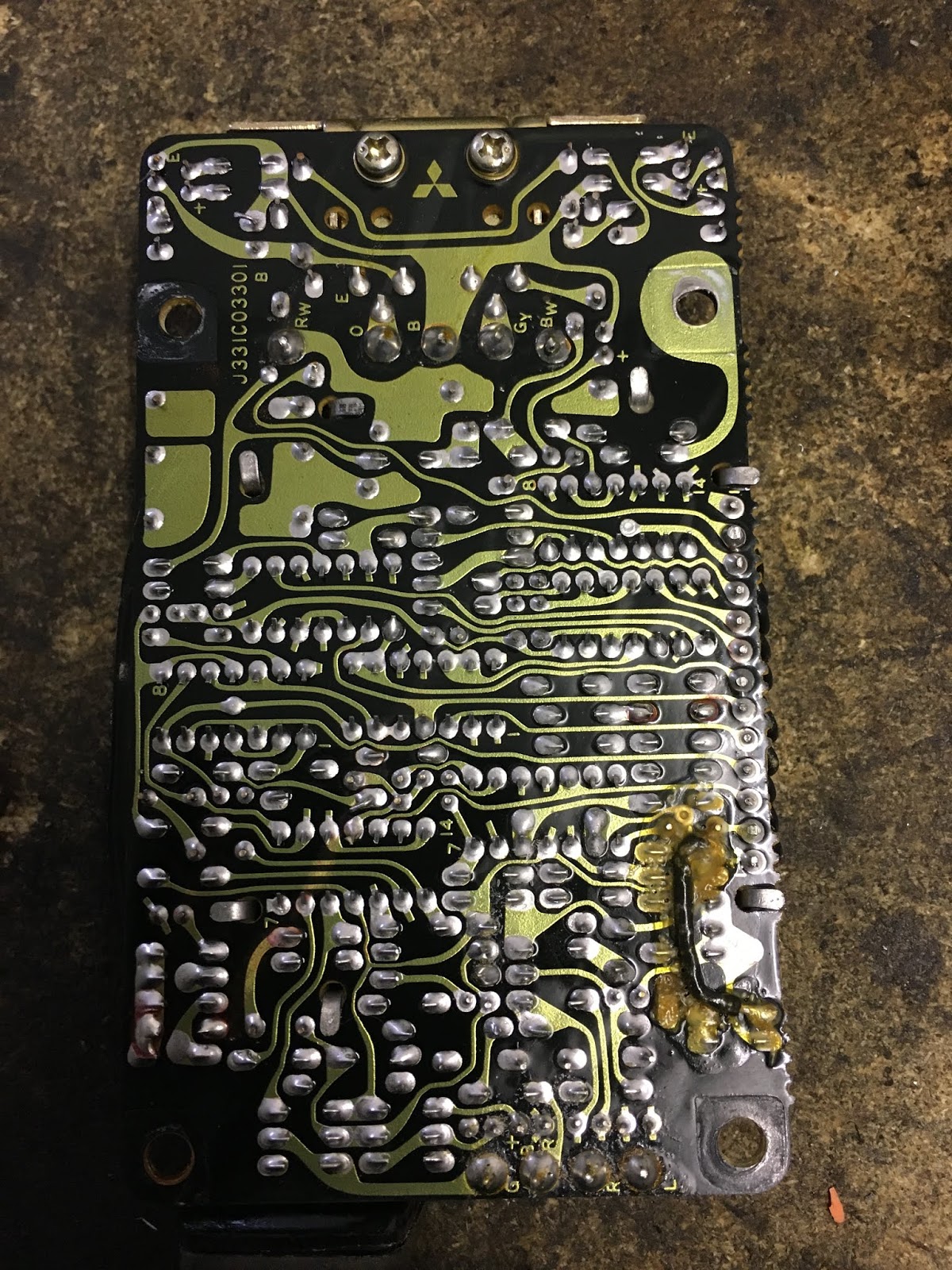
Hard to believe, but the later box does the same with just two Mitsubishi M59201P chips and as such wasn't only a lot cheaper to manufacture, but more than likely also should be a lot more reliable. (As is perfectly contradicted by this one being broken...)


My main focus in the coming posts will honestly be on the metal enclosure TCI, because first it's the one I run on both TR1s at the moment, second I already identified all the capacitors for it and I also got some replacement transistors (as I suspect one of them being broken) and lastly because the second type is both rather uncommon in Europe (at least I haven't encountered it a lot) and you can still buy it new for a very low price. (Which I may do as the Mitsubishi IC isn't available to the public anymore easily and I would really like to see what the manufacturers use to substitute it with...)

Next post will be on how to free the boards from its metal confines and a bit more in-depth analysis.

Wednesday 1 January 2020

Project outlook 2020

I don't do New Year's resolutions, but I did a bit of planning and maybe this will give you a bit of an idea of what to expect.


XS-Triple-Sidecar
I'll postpone the engine-build towards Summer as the engine is running fine and not consuming as much oil as I dreaded. What I will tackle though is the swap to go to some Mk.1 GSXR750 flatslides. Mainly because they have an accelerator pump and this will allow me to run them a bit leaner overall and thus get better mileage. Even though, when used sensibly the sidecar is doing quite well with under 9L/100km considering it's size and frontal cross-section. Also I am still looking into the option of building a battery tray for a car battery as I hope to attend a certain winter motorcycle meeting in the Alps and a bit more starting power won't do harm. (And I already have all the parts necessary, I just have to find time to do it.)

Everyday TR1
Expect a post on how to overhaul the stock TCI (ignition box) rather soon, including lots of info you never wanted to know about how it works and which other cheap options you have for TCIs and other TCIs that will actually fit with rather minimal hassle.
Addendum: If you have a broke XV500, 700, 750, 920, 1000 or 1100 TCI and want to get rid of it, please let me know. I can't promise a repair, but it will definitely help with research.


Turbo
The turbo will move over to the other side of the engine, where it is less intrusive and the oil-drain is easier and I really want to road-register it. I haven't fully worked out the how, but I have a few ideas. This will obviously also involve some work to get it road-worthy in a more traditional sense (indicators, horn, etc.), but if that's what it takes...


Dre-XT-Stück XT600
This old girl is actually mostly done. It will get a sprocket support bracket rather soon, a bit of tweaking on the carb and the rear-shock and I will adapt a pannier rack to increase the everyday-usability-factor.


Other projects
The Stinkerle shall be brought into a running state rather sooner than later and then its future fate will be decided. And then there's a special project I am doing with my dad, which currently ranks highest on the priorities' list, but as it is top secret I can obviously not give away any infos. All I can tell you, that its fairing and accessories almost way the same as the complete Stinkerle.

So there you have it -  what's to be expected in 2020. (At least the stuff I know already.)