Thursday 31 March 2016

The Turbo TR1 (part 5) - headers are the spaghetti of doom


 Just like on a naturally aspirated engine the overally performance is vastly affected by how well thought out the exhaust header design is. On the TR1 it is (even more than on other bikes) a balance between performance requirements and packaging.


 For example a 90 degree bend right after the exhaust is definitely not the best one can do, but it is the only way to join the two header pipes together without creating terribly long downpipes and thereby wasting precious gas velocity and therefore energy that should be used to spool up the turbo!

The chosen diameter for all the pipework is a mere 40mm for exactly the same reason. The smaller the pipe the faster the exhaust gas will flow and thereby transfer more energy onto the turbo's turbine and hopefully spinning it faster.


 It may not quite look like it, but the two headers are almost the same length and as short as humanly possible without interfering with either the fuel tank, the cylinders, the frame or the rider's knee. 

 Front view. It never ceases to amaze me, how narrow a v-twin engine is...
 With the frame backbone bolted on.
 And the turbo clears the fuel tank (just)!

 And that's a few weeks later with the new forks in place, new tyres and even some paint gently applied to the frame and tank. Oh and let's not forget the huge K&N filter.

... and that's pretty much all there was to it, when it comes to turbo headers!

Tuesday 29 March 2016

The Turbo TR1 (part 4) - building the mother of all evil

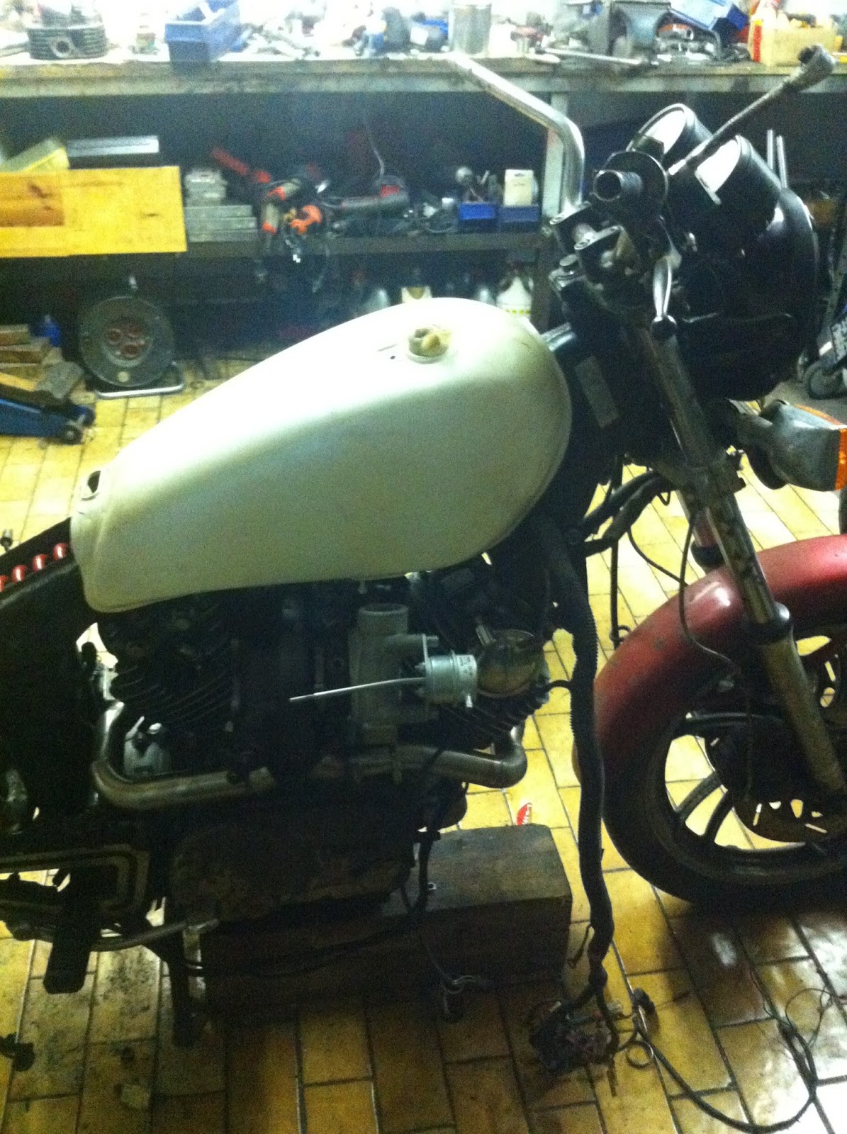
With the stock innards assessed and the XV1100 engine parted out, it was well about time to build the future mother of all evil. An engine capable of handling a bit of boost.

As you've already seen the three-leg-puller the only other special tool you'll really need on the lower engine case is this L-shaped plate used to push out and pull in the crank. The studs are M8 and with a bit of measuring it shouldn't be too hard copy my design.

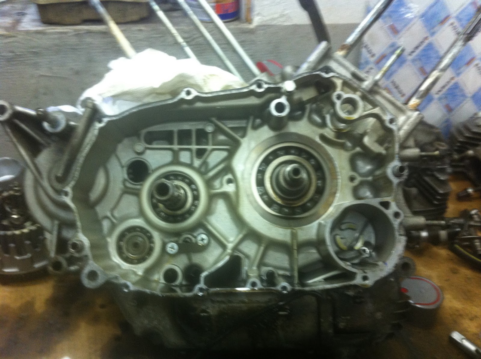
The two inner bolts push against the face of the crank bearing and thereby sparing you from removing (and ruining) the oilpump sprocket on the crank taper. The cases should be heated properly to facilitate crank removal and prevent the bearing seat from damage.
 XV1100 crank inserted (it will go in a little bit)!
 Securely tighten the crank nut against the L-profile and then pull the crank into the left case. Make sure you go half a turn left and then half a turn right to make sure the crank isn't pulled into the cases at an angle.
One other thing to pay careful attention to are these little red o-rings. They should be replaced with new ones, when the pump is removed as they ensure a pressure-tight seal between the pump and the engine case and any pressure loss would be very hard to notice, yet could quite easily kill the engine in a rather short period of time.
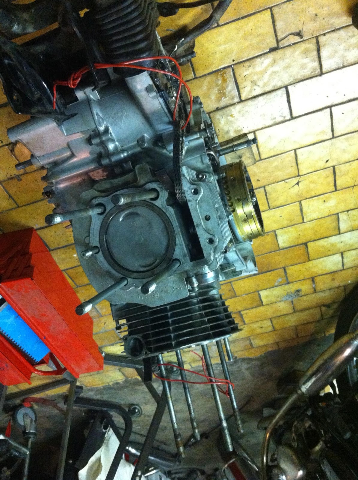
 Right side timed up and the clutch basket installed.
 Timing the left side is a bit tricky as you can't really see the marks on the primary drive as the view is obscured by the rotor. But checkout the hole at the 1 o'clock position, you can *JUST* see the correct teeth meshing, if you blacken the corresponding teeth on the gears.
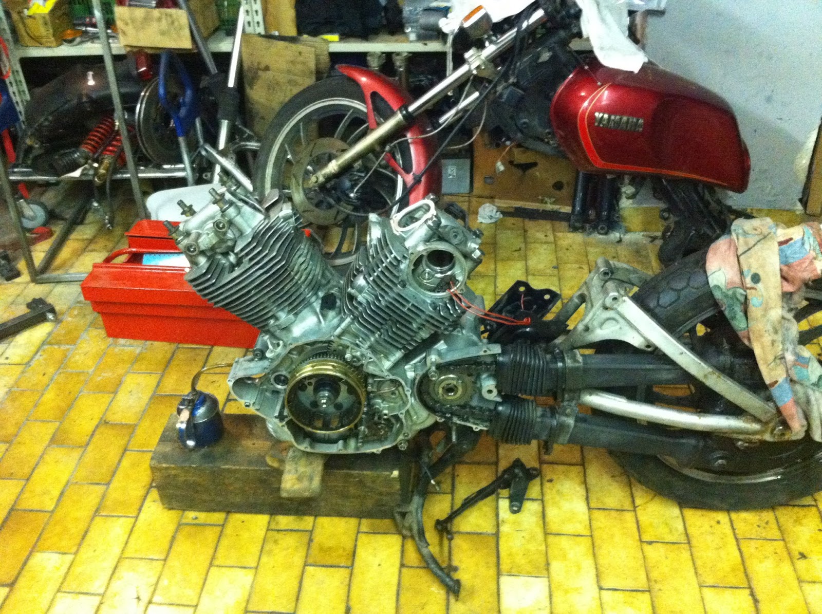
 That's the engine bolted up to the lower rear subframe.


The head shown is actually one of the stock TR1 heads taken from this engine, but with polished inlet and exhaust valves. Basically showing that it isn't as pointless as a lot of people say to polish valves. The hotter exhaust valve was (as you can see) still quite clean, even though it had done more than 10,000km. The valves on the 1100 heads were finished the same way. 


The cylinders are installed.
 And the heads are back on.
 And that's the heads installed.

Truth be told those pictures were taken almost two years ago and then the engine and rear subframe went into a long hibernation period, where it mostly served as a jig for building TR1-exhausts...


Sunday 27 March 2016

The Turbo TR1 (part 3) - parting out a perfectly good XV1100 engine

Next on the list was to part out a low-mileage XV1100 Virago engine, which I literally only bought for the crank, pistons and cylinders. As it turned out, the pre-owner's claims that the bike was set aside because the shaft drive coupling broke were actually true.

Both sidecovers removed and one can see, why you can't use the XV1100 rotor on the TR1 - it's a lot bigger and only has one nose to trigger the ignition.

 A universal three-leg-puller plus a bit of heat (best with an oxy-torch) and the rotor will pop right off.
 A XV1100 gearbox in absolutely pristine condition. This will go in the everyday TR1 in 2017, I guess. Not because its gearbox is bad, but the 1100 sports a longer 5th gear and altering the final drive ratio AND maintaining the chain enclosure in one go is unfortunately impossible.
The XV1100 crank, a bit over 12 kg of rotating mass - 1.8 kg more than a stock TR1, but also 5mm more stroke.


Friday 25 March 2016

The Turbo TR1 (part 2) - disassembling the stock engine

As I pointed out in the very first post regarding the turbo bike, it came to me almost for free, mostly because it was in a terrible state and due to the seized engine. 

 Nevertheless it was said to be a very low mileage bike, so I was somewhat hoping that I could still salvage some good parts. I was absolutely right about that. After a bit of cleanup and new valve stems, the original heads went onto my everyday TR1 and served me fine for the whole season.
 You could even see the honing cross hatch marks on the cylinder bore, indicating that the around 30,000km on the clock must be about right.

With the frame lifted off the engine and heads and cylinders pulled there's only four bolts holding the swingarm onto the engine, which makes the whole lot quite easy to handle. 


The whole lot on the workbench, clutch and primary gears for the front cylinder already removed.

 Right side of the crank case lifted off - still no nasty surprises.
 The otherside of the right engine case.
 And the left crankcase side with the rotor, oilpump and rear cylinder primary gears removed .

Wednesday 23 March 2016

Some general tune-up and and welding a bung in for the AFR-meter

Recently I was asked on a forum, what my stealthy VM38 setup looks like, which coincided very well with some re-jetting work.

 One of the extremely convenient aspects of VM38 carbs is that you can in fact change the main-jets without removing the floatbowl. Unlike when you want to change the pilot jets as they are countersunk in an orifice.
 VM38s sport a brilliantly unique float arrangement.


Bungs for AFR-meters can be bought via various sources. So called Lambda-probes usually sport an M18x1.5mm thread (there's a smaller M12 based version as well, but these are less common!) Usually these rings are around 25mm in outer diameter with a lip, which is a tad bigger. 

 Mark a suitable spot on your down pipe and remember that the Lambda-probe should be angle downwards, so that potential condensation won't pool up inside the probe.
 Drill an as large as possible hole (my biggest drill was 17mm) and then use a die-grinder. Once you're getting close check all the spots where the bung and the pipe touch, the better the fitment, the nicer the corresponding weld.

 Not exactly the nicest weld in the world. :-)
 Oh and a word of warning: NEVER fit a cold plug into a hot threaded bung. Feel free to guess how I found that one out.
 And installed again on the everyday TR1!


Monday 21 March 2016

Ignitech programmable ignition on the everyday TR1

My everyday TR1 is not only one of my preferred rides for commuting, but also my test-mule for the turbo-project. After suffering from some ignition issues, by the end of last season, I reverted from my Ignitech TCI-P4 box back to the stock ignition, which in fact was a bit of a shock, mainly because I had fine tuned my Ignitech a lot. And just to save Ignitech's reputation, before you even doubt it, it was a duff crank position pickup that caused the box to lose its position.

The box itself looks very unassuming, but has got a RS-232 connector on the back.
 All you need to program it is a USB-to-Serial-connector cable (mine's from Prolific) and then turn on the ignition so the box is powered up.
 Furthermore you need Windows of some sort. I am running this on a virtual machine, as I run Linux on the workshop pc. And ontop of that Ignitech's Sparker software in the matching version for your hardware. At the moment this is Sparker-TCI v.88.
 Hit the read button and you're presented with the preset curve, save that as a reference and play around with the curve. The curve below is far from optimal and produced a notable bit of hesitation when accelerating as it was advancing the ignition quite violently.
Now check out this curve: Generally you'll only want as much advance as absolutely necessary, as too much ignition advance will lead to pinging (detonation) and make the engine run hotter than necessary, which is a bit of an issue with my TR1 engine anyway. Especially now that I've raised the compression ratio to around 10.3:1 from the stock 8:1 ratio.