Monday 31 December 2018

The Norwegian Job - an engine for Faffi (part 1)

So my mate Faffi fancies a fast TR1 engine, but for one reason or another he can't get his hands on anything decent and I have my old TR1 engine sitting on the shelf. A bit of chit-chat and one thing leads to another and he buys the complete get-out-of-jail-and-enjoy-some-horsepower-package.

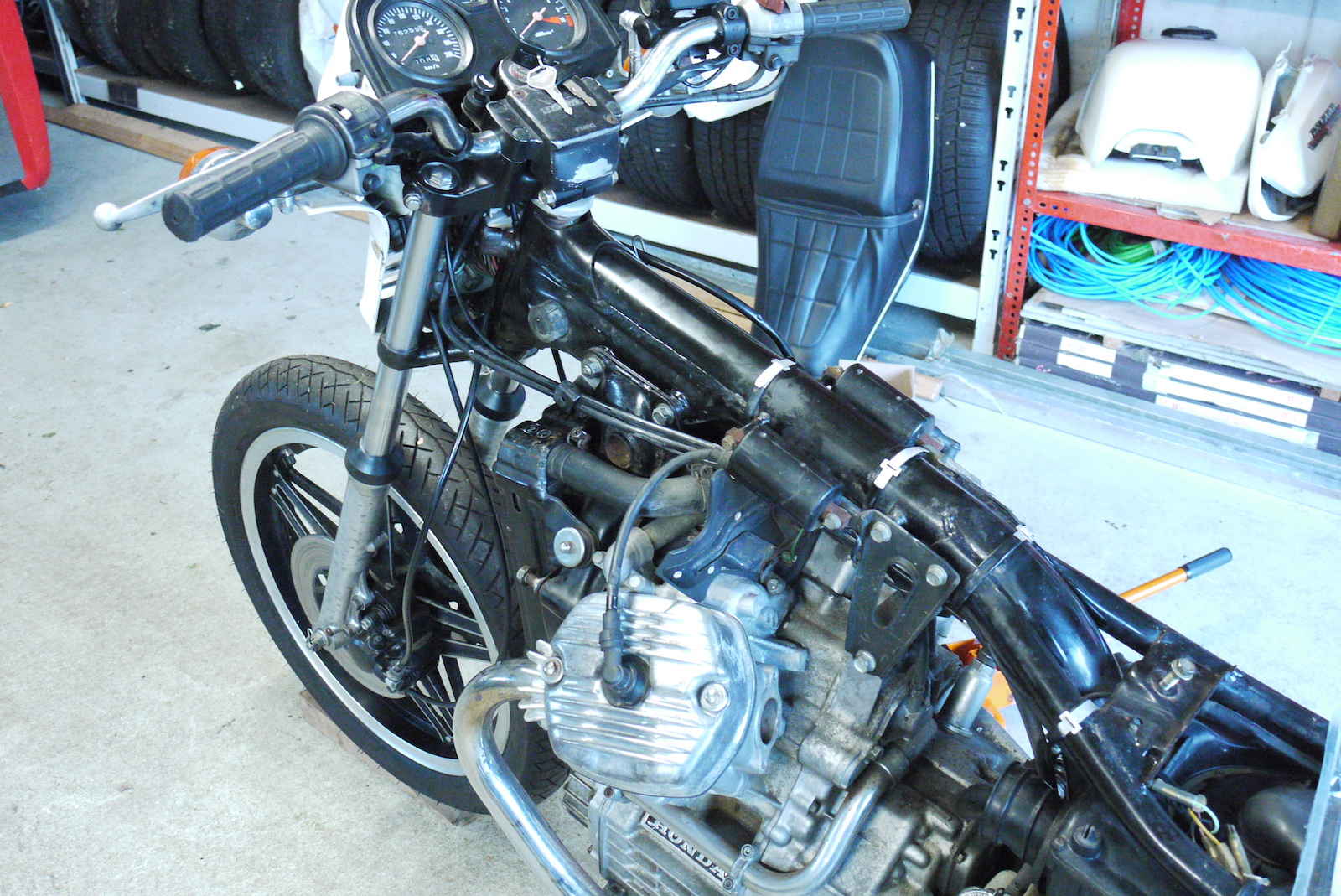
Part One is basically the disassembly story and part two will be the reassembly and (test-)installation in my Turbo-TR1-chassis to make sure everything works as it should.

Just to give you an idea: The engine is my trusty old Everyday-TR1 original engine with roughly 110,000km on its back, which was running fine except for a bit of an appetite for oil and a slight knock, which I originally tracked down to the bottom end and some "not-quite-so-slight" oil-leakage from the rear cam-chain-tensioner. (Which was just down to a torn gasket, that I might have missed for a while - it's also very hard to get to, because obviously it was on the rear cylinder.)

Step one was to drain out the oil as good as possible. As you will see by the oily-rags, we didn't exactly a good job on that. We being my dad and myself.


Using the term "cleaned" might be a bit much, but the worst oil and grime has been rubbed off from the top half of the case.


Put the rear cylinder on TDC to make disassembly a bit easier and also to check for camchain wear.


Near perfect - there was some stretch in the camchain, but as I replaced that two years ago (or so) that hasn't stretched any more than the initial stretch.


Even though it should be fairly obvious, I like marking the brackets on the rear cylinder left and right as it avoids a lot of confusion.


No point in denying that this engine enjoyed a sip of oil every now and then I guess. To be fair at this point I dreaded the worst like broken rings or the like, even though the cylinders looked absolutely fine, you could even see a bit of the original crosshatch pattern here and there on the cylinder walls.


The front cylinder looked slightly better, but with that amount of oil-buildup on the piston it came as no surprise that it was knocking a bit, when really, really hot.


With the cylinders pulled from the engine, it was about time to give the rods the casual "pull-test" and nothing really moved. I was planning to do the conrod bearings anyway, but most likely, if this still were my own engine, I'd left the bottom end as is as there was no immediate need to do anything. (One thing I really didn't notice, when pulling apart the engine is that the squish actually worked nicely in pushing the mix away from the cylinder wall as you can see in the clean spots on the side of the pistons.)


I decided to do minimally-invasive surgery this time, which means leaving the crank in the left crankcase. Still this meant fully stripping the right side and at least removing the oil-pump on the left side.

Also in the picture my very first modified 9-disk-clutch. (Still a thing o' beauty, if you ask me!)


Left side, with the shifter mechanism already removed. Contrary to popular believe it is quite doable to remove the oilpump, without removing the rotor, when you undo the single philipps-head bolt that's holding the pump together. 


As can be seen in this very arty out of focus picture. 😇


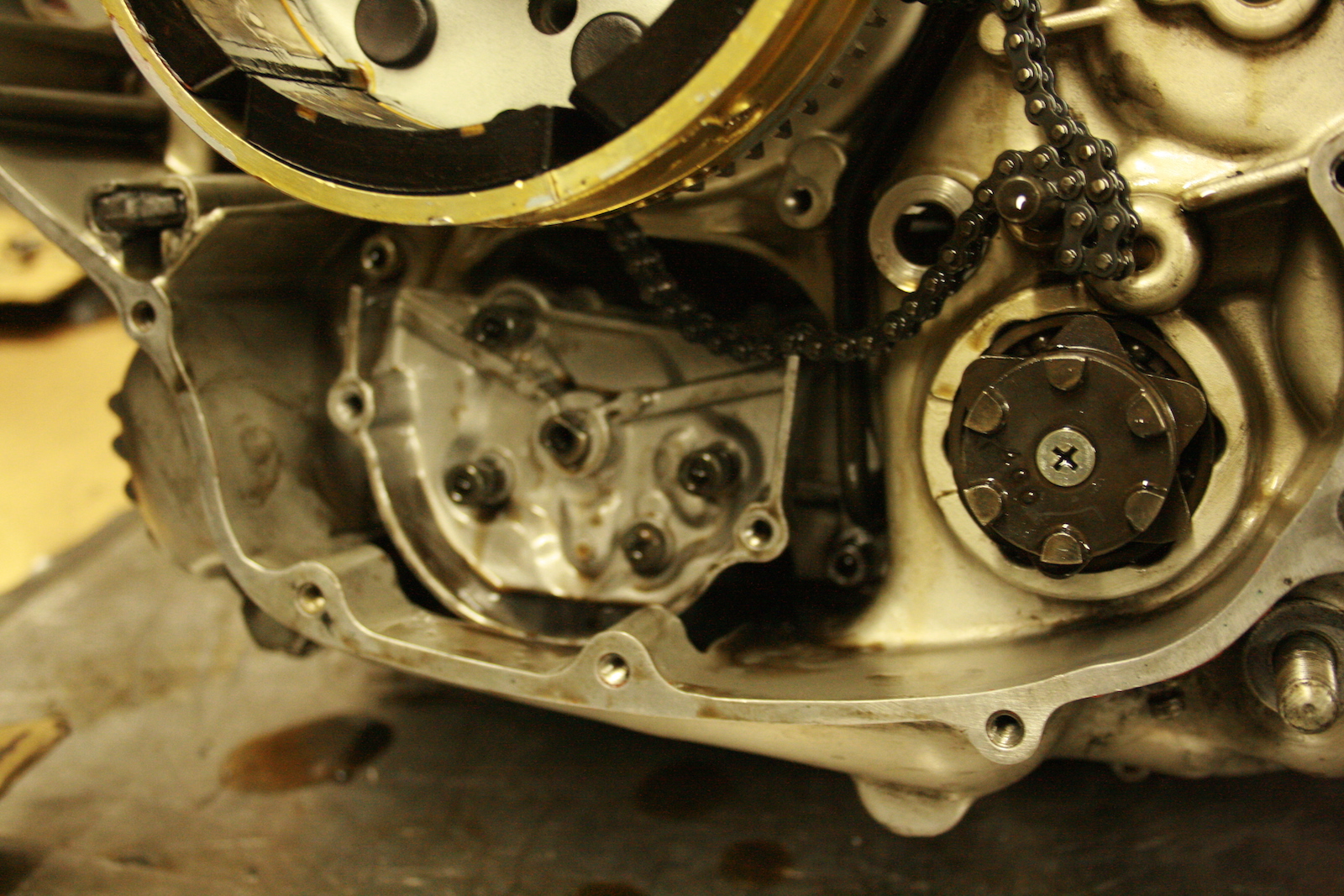
With clutch and right-hand primary drive removed it's a simple case of removing all the bolts holding the engine together. (Note the three bolts INSIDE the engine, one of which is hidden behind the oil-pump!)


Fast forward quite a few minutes and we have the engine case cracked and the conrods removed from their place. It can actually be done without removing the crank from the cases, even though it is much easier with the crank out. That being said in order to reach the nuts for the rear conrod, you have slide it up and put a bearing cap back in as a spacer, so you don't twist and turn anything.


Now the hard lighting makes the bearing shells look a lot worse than they really are, but there's no doubt they've covered their fair share of miles. Still the crank looked like new and after a short casual glance at the spec-sheet a two-size smaller set of shells (black instead of green for those, who want to know) was selected. 


And that pretty much ends the whole operation for 2018. Conrods have been re-installed and tightened to spec, gearbox is back in after finding NOTHING out of the ordinary, not a single gear suffers from pitting or worn gear dogs and can simply be reinstalled.


So all that's left is to clean up the mating surfaces a bit more, oil the gears and bearings and put the bottom end back together and wait for the sealant to cure. Once that's done the outside of the engine will get a good wash to look representable again. In other words, what does it take to run a (tuned) high-comp, long-stroke TR1 engine for another 110,000km? A set of bearing shells and some fresh rings, because quite honestly, that's the only thing really amiss on this engine. The oil-scrapers have the equivalent amount of tension of a worn out elastic band.

Monday 24 December 2018

More carbwork - both on the TR1 and the XS-Triple

Theory is when everyone knows how it should work and it doesn’t, practice is when it works and no bugger knows why.

It's time to put some theories to the test. 

In my last post, I went on and on and mentally m*st*rb*t*d on how to jet carbs. Now this didn't all come out of thin air, but stemmed from some minor problems I have with my TR1 flatslides and some rather bigger problems on my XS-Triple sidecar. 

As I outlined, if you run a needle with the wrong (too shallow) taper, you will always encounter a rich or lean situation along the way. In the case of my TR1 it was most prominent the first 1/4 of throttle opening, which I countered by running a slightly bigger pilot jet (#20). This worked fine for obscuring the problem, but meant that when the engine was really hot, it would pop and cut out and also result in some detonation issues, when hot. 

I chose the 6FJ40 needle, because honestly, I knew I wanted it to be richer than the stock 6FJ41 and it was the only one of the needles that I could get some specs for. It might be a bit more than needed, but then again, this is also the needle that's fitted to the two-stroke version of the TM38-carb.


On the top you see the 6FJ41 needle, on the bottom 6FJ41. As the latter looks a lot more like the 6DP01, that I've run in my old VM38-9 roundslides, I think, I might be on the right track though.


The verdict of the jury is still out on this one, but I decreased the size of the pilot to #17.5 straight away and hope for the best. (And no salt on the road.)

The second part I've been playing around with lately were the flatslides on the sidecar. Mainly because I had some serious fuel-supply issues, which manifested in losing idle after a prolonged bit of full-throttle. Personally I think the following pictures don't need a lot of explanation. Except that I now run an incredibly complicated fuel hose setup as each of my new petcocks has got two outlets and I therefore run 4 lines and 4 filters. (It's only a matter of time until something starts leaking, but to be fair, I only have to get some T-pieces and revert to my old petcocks to remedy that.)


See these puny holes? No wonder I could put on my helmet and gloves, while priming the carbs... 


That's more like it.


I tried that out yesterday and guess what, THIS WORKS. Open the petcocks (on dry carbs), wait for a second and then fire 'er up and off you go. Next stop: solve the jetting issues, as she's a bit cold-blooded at the moment, but I think, I have just the needle for that... 

And in this sense: Happy Jewish Zombie carpenter birthday. Merry Christmas. Gud Jul. Frohe Weihnachten. Or whatever you're into on a day like today.

Friday 14 December 2018

Carburettors - more than you wanted to know (using the example of Mikuni TM38s)

Now there's plenty of good and some really dreadful advice out there on how to setup carburettors and yet I plan to add one more to the list, mainly because I haven't found some good info on how to set needles correctly, because that's usually where most people tend to go "a bit funky" and just mess around to the best of their knowledge.

At first, let's flog a dead horse by having a look at the following schematic:

Source: Mikuni Corp, 2012
As you can see, this is a slightly newer version of this well-known graph that contains diamond-shaped indicators to highlight the fact that a carburettor will NOT digitally switch over from one jet to the next, but that multiple jets (within reason) affect the performance at various points in the slide lift. (And that's completely omitting the fact that the engine has rather varying air- and fuel demands depending on the terrain you're driving on!) But there's more that's missing in the graph, because it assumes that the setup is correct. Not to worry, we'll get to that point.

Let's just simply follow the carb slide through a usual day at work and identify the problems I encountered. (and most likely you did too, because quite frankly otherwise you probably wouldn't be reading this!)

For coldstart we obviously need to pull the choke knob and enrich the mixture and then run the bike (mainly) on the pilot jet and the additional choke jet. There's mainly two things aside from the choke affecting the mixture at this point and that's the pilot jet and the slide cutout. (called throttle valve in the schematic above) Now it should be obvious that the smaller the slide cutout the less air goes through at the same height of the slide, also the slide cutout basically determines how steep the curve rises that determines how much air gets to the engine at very low slide opening. This (within the limits of the engine) determines how "snappy" an engine will feel to the user. Additionally a smaller slide cutout will help to keep things more moderate and make jetting the pilot easier.
Real world example: a VM38-9 has got 2.5mm slide cut-out and a TM38-86 has got 4mm. The jetting on a Yamaha XV1000/1100 engine is pretty close in both instances, but trust me, a TM38 with the bigger slide cutout will feel a lot snappier.
Pitfalls (or also why you shouldn't start jetting from the bottom up): For rather obvious reasons it would be very tempting to start jetting from the bottom up, because then even if everything else fails, you at least would end up with a decent idle. And here comes the catch: as I pointed out before the schematic above only applies, if everything is working perfectly and even then the whole system is rather dynamic, meaning if your jetting is off, it simply doesn't add up. Assuming that for example your mainjet is dramatically oversized, it will overlay and obscure incorrect (lean) jetting in other areas. The art of jetting carbs is knowing some recipes, which usually work and then apply some common sense, e.g. if you run a #300 main-jet and the smallest pilot jet IIRC a #12.5 and your bike is still running so rich it will fire up without using the choke, there is a strong reason to believe that maybe your pilot jet is not the reason. Let's assume you get past this point and your jetting is somewhere in the vicinity of #20 pilot and a #185 main-jet. (Seems to be roughly the golden numbers for a Yamaha XV with a TM38, when sucking through the frame with a correctly sized airfilter and a free flowing exhaust.) Yet still it seems to idle weirdly when cold and once hot it will race to stupidly high rpm or even worse, when really hot will fall on its face again and not idle properly. The next thing is to look at the slide height: One of the standard pitfalls to compensate an overrich pilot is to raise the slide until it will idle just fine. This will then result in climbing idle for a bit only to have the bike lose idle once it has warmed through.


Next let's look at mid throttle openings. As stated before when the slide opens, the slide cutout is the main determining factor for how quickly the amount of air increases that gets into the engine. In parallel, as can be seen in the picture above, the carb needle isn't a straight control rod either, but is tapered. And now this is where things get tricky, because there's a lot of things that can be adjusted at the same time and even though on paper the results in AFR will be comparable the consistency of maintaining said target AFR. This brings us to the resulting question: Which options are there and what does what?
  1. The needle taper controls the steepness of the curve (progression). A thinner needle will mean a richer initial mixture and depending on how steep the needle is, it will mean also affect how rich the mixture is at max. slide opening and thus affect the main-jet.
  2. The clip position will set up where the starting point on the taper is. This can be very helpful, if you run a needle with a relatively flat taper, but almost impossible to use with a needle with a steep taper as even small increases dramatically change the effective diameter of the needle in the needle jet. (And that's completely ignoring the effects of worn carburettor needles, which may have a ridge worn into them at one point...) It has to be noted that some carbs come with needle shims to somewhat compensate for this, when quite literally the setting changes that can be achieved with the clips are too coarse.
  3. Lastly the needle jet, this is the only linear modifier in this equation. A bigger needle jet will quite simply increase the amount of fuel all the way from bottom to top. 
So in order to choose the right needle, needle-jet and slide combination a bit of seat-of-the-pants tuning is mandatory. The easiest case would be that for some reason your bike idles like a champ and once the revs have climbed sufficiently full throttle makes your bike go like a scalded cat. What you would do next is to lower the clip a bit and see if that improves the situation. For reasons outlined above that will improve pickup at  low to mid throttle openings, but will maintain a large gap at 3/4 throttle until it picks up and it runs nicely again on mostly the mainjet. So you lower the clip once more and now it's better at the last bit, but all of a sudden it falls on its face up to about half throttle. What you established now is that you need a bigger needle jet and then have to re-check, if the needle taper matches your desired engine characteristics. You could try to off-set the situation by running a smaller pilot jet, but this will lead to a much inferior idle, in the sense that it will become very temperature-dependent. And this is where the varying tapers also come into play. The exact tapers for a certain are simply not published, so you have to get your own micrometer out and determine what you have in your carb and then get a needle that matches the data as close as possible.

Source: Mikuni Corp, 2012
As you can see this list contains the recommended needles for use in a Mikuni TM38. All of them are from the #6 family and the leanest three are of the 6F-type, meaning their initial diameter is 2.522mm. The subsequent letters and numbers outline where the taper starts and how steep it is. Also just to confuse you: the code overall doesn't say anything about the length as these are all around 68.x mm long, whereas a 6DP01 is 62.2mm long. After doing quite a bit of extensive research on the difference of the two-stroke (snowmobile) and four-stroke (TM38-85 and -86) variants of the TM38 carb, it turned out that there literally only where two main differences aside from main- and pilot-jets that catered to vastly different fuelling requirements. Basically what Mikuni did to turn a TM38 into a two-stroke carb was to add a slightly richer needle and install a restrictor into the air-port in the back and thus making the mixture a lot richer at part throttle. (Which is where most seizures on two-strokes happen during the setting up of carbs...)


The last stop in our journey is full throttle. Even though this is the point, where the most can go wrong, it's also the easiest to jet. Following some gutt-feeling and experience one usually starts this "a tad" richer than is expected to be right and once the bike has warmed up, literally just hammers the proverbial snot out of the engine by doing full throttle pulls. Installing smaller mainjets until the performance can be felt to go down, pinging occurs or the oil-temp goes through the roof. (Usually it''s a combination of all three, but with a bit of careful testing one can keep this within safe limits at the very first point of the list.) With the orifice of a main jet being so vastly bigger than all of the other jets that's also why you usuall start there and try to get the mains right for a start as mistakes there will trickle down all the way and even affect pilot jetting.

So where does this post come from: Basically I was trying to organize my thoughts and trying to work out, what exactly needs to be tackled to get the TM38 carbs on my Everyday TR1 working perfectly. The situation is as follows: Bike idles fine when cold and up to a certain temperature, even though the RPMs vary a bit, once really hot (as in above 110 degrees C of oiltemperature) it completely falls on its face and will only idle when the slide is lifted a bit, clearly indicating an over-rich pilot. At the same time when up to temperature, there will be a certain amount of pinging at low (1/4 to 1/2) throttle opening indicating a relatively lean mixture at that and the mainjet is quite substantially larger (#185) than on my old VM38-9 carbs (#165), even though the effect is less felt at wider throttle openings.
Following the long winded text from above everything is pointing towards a somewhat too lean needle and as the problem isn't really linear (especially as the main-jet is actually about right, keeping the engine oil-cool, no detonation, power seems about right and the plugs aren't fouling), it all points towards the needle I am using isn't perfectly right for the application. As I actually ordered the new needles before finding the chart above, I now have a set of 6FJ40 needles to play around with. (Once the snow and salt are gone, some serious testing will commence!) I expect to finally be able to decrease the size of the pilot by one size and go back to a #20 and overall experience lower engine-oil-temps as the bike isn't running on a lean midrange.

Friday 7 December 2018

The Turbo TR1 - new manifold (part 4)

Slowly, but steadily this stuff's coming together like it should... to admit I am a bit excited by now is a wild understatement. It all seemed rather theoretical up to now, but by now it's basically down to finishing the oil-suppy and then find out which parts I robbed off the bike in the last one-and-a-half years. But I am getting ahead of myself.

First step was to clock the turbo, which is a dead simple job on a new turbo, but a lot less so, when years of caked on oil and diesel-soot glued the whole lot together for good. Weeks of penetrating oil, a heat gun and some (not overly) gentle taps with a Newtonian particle accelerator (a PROPER rubber mallet) and it finally freed up. And just to give you an idea, just how small that lil' turbo is – that's a 10mm spanner below it.


Following the tradition of this being a proper parts-bin-special, this is a wastegate actuator from some Volvo (I think) with a GT1752 as the original actuator worked from vacuum and not boost, because it was operated by the Opel's ECU and not directly. (They were waaaay ahead of their time back then...)


A bit of fitting up of all the components and that VERY satisfying moment of: it's tight, but all fits in there... somewhere.


From a design point of view, this has got to be the single most elaborate plenum/intake manifold, I have designed to this point. It's every bit as three-dimensional as you would think, when looking at these pictures.


And that's actually the fabrication side of things on the cold side of the turbo mostly done.


So what's still missing at this point: I have to drill and tap the compressor housing to get a boost-source for the wastegate-actuator, sort out the oil-lines (both feed and drain), tap the engine case for the oil-supply and then sort out all the electrical gremlins that mostly stem from me "borrowing" parts for my daily and friends' projects.

I do not see a silencer as a high priority item. 😉

Sunday 2 December 2018

Phour days to phantastic - a Honda CX500 tale (day 2)

Now let's start out with the fact that it's no longer about doing it in four days and also not (quite) in four consecutive ones. Let's more aptly call it "phour installments to phantastic".

Regardless of what you see below, I would like to point out, that the bike ran last time, before we, being my dad and me, pulled the carbs out. Tough little bugger.


Out comes the ultrasonic cleaner and trust me it took waaaay more than one attempt and fresh cleaning solution to get to clean up. 


Now I have pointed out, that this CX was rather well-priced. Not much of a surprise as we had to go through all the de-mobbing paperwork of an ex-police bike, which strictly speaking shouldn't be registerable anymore and on top of that it must have had at least one incident of rather unconventional parking, i.e. a crash. As such we used the time rather well in trying to re-align the engine and frame after loosening the bolts last time to swap the front engine cover. Luckily there are no pictures of two adult men wrestling with 2m tubes trying to force the engine back into position...


In the end the carb came out a lot cleaner than before. Which didn't help much, because the following jet disintegrated and took the left carb body with it. 


So second go with two new jets (one as a spare) and a N.O.S. left carb body. 


The following picture is meant to help all of those, who are trying to piece together a set of these Keihins. There's umpteenth springs in this picture.


Because technically it was a new day, I had also bought all new stainless hardware, I mean no reason NOT to dress up a turd, right? 


Some people say you have to put a bit of yourself into a project, when you want a good result. The red stuff is blood. Carbs are in, new engine manifolds and all looks pretty decent to be honest.


Well, pretty might be a bit much to ask for, but that's the bike completed and ready to fire up.


... despite it being less than zero degrees in the workshop, after a few moments the poor man's Guzzi came to life again. A few tweaks on the idle screw and she idled with a bit of help from the choke at around 1700-1800rpm. It's hard to tell as it was so cold that the tach was more or less stuck and wouldn't really respond to changing revs.


Aftermath: After a bit of checking, there were no leaks or unusual sounds and the bike seems to run ok(-ish), which is totally fine as the carbs aren't sync'ed or the mix screws set up to anything close to what the book says. All the electrics seem to work (except for the temp gauge) and it charges just fine. Next step will be to get her fully road worthy and registered. And at this point I hope my dad will put her to good use and then the last installment will be a slightly less hideous tail-piece and seat.

All of this will have to wait though, because right after we took the last picture snow began to fall and that basically renders any road testing impossible.