Wednesday 27 April 2016

Everyday TR1 - vacuum ports

One of the (very few) let downs with the VM38-conversion on the Everyday-TR1 is the fact, that I had to sacrifice the original inlet manifolds with their vacuum ports. This in turns meant that I was (up to now) only able to sync the carbs the oldskool-way with a drill under the slide and adjusting the cables to suit. This did indeed work quite well, but after recently adjusting the carbs on a mate's BMW 2002 (without) and especially a Guzzi V7-700 (with vacuum ports), I decided that vacuum ports are actually a must have.

The task itself is nothing to write home about:

1) remove the carbs and put the cylinder you're working on TDC, to make sure the inlet valve is closed and stuff some rag (or paper towel) into the inlet.


 2) punch-mark a suitable spot on the head
 3) go at it with mad force (and in my case a 5.5mm drill)
 4) I used some 6mm o.d. stainless tube, which does fit snuggly with some persuasion (i.e. a big hammer and a drift)
 5) I then followed the Guzzi-Manual for adjusting the carbs and set the idle screws with the gauges hooked up to have both cylinders idle at EXACTLY the same speed. So far I only did this by ear and I have to pat on my own back - I was mighty close. Yet still, the idle is now without any popping or farting.
 6) Next step was to adjust the cables to be in perfect sync by turning out the throttle cable adjuster on the throttle housing until the revs lifted slightly, meaning that the cable lifted at least one slide off the idle adjuster, which is just a positive stop for the slide in the carb body anyway. From then onwards it took some fiddling and fettling until I got both carbs right.

Conclusion: It did make quite a difference so far. Mileage has improved notably and I found out that as soon as both cylinders are working as they should, my pilot jets proofed to be too big.

Things I did modify afterwards: I pulled out the vacuum tubes once more and countersounk the holes a bit and then filled the groove with epoxy to improve the seal on the rear cylinder. When the bike is really, really hot I am under the impression that it sucks in some air on the rear cylinder. Nothing dramatic, just a little mod to improve stuff even further.

Sunday 24 April 2016

Everyday TR1 - clutch mods

Originally I always intended to use the bike that eventually became the Turbo TR1 as my test-mule and if the mods work out, transfer them to the Everyday-TR1. Well, things don't always go to plan, do they?

Two things bothered me seriously last year: firstly the bars on my Everyday-TR1 as I just couldn't find any that were both comfortable on the neck and my wrists (after dropping my bike about two years ago and bending the bars that I had fitted back then)  and secondly the heavy clutch-pull.

With the bars sorted last time, this mainly left me with the clutch. As I pointed out a while ago, I milled the inner clutch hub's spring posts flush with the outer ring. (I thought!) Turns out, I must have milled them down too far and in fact they were about one  millimetre below the outer ring. This in turns means that I had an extra millimetre of preload on the springs (which were stiffer aftermarket items as well!) Plus, I had put a washer on the springs adding another mill of preload, all of which resulted in a VERY MANLY clutch-pull.


Now the lesson learned is: my spare clutch basket will be milled down to one millimetre ABOVE the ring and put this clutch basket into the Turbo TR1 as that will need any bit of clutch pressure it can get.

So the solution for now is not very elegant, but successful: I swapped the washers around and now there's about three millimetres less preload or in otherwords, approx one mill above the ring.


Thursday 14 April 2016

Everyday TR1 - gets a little makeover

Now I only very recently fitted a new tailpiece puzzled together from leftover XS400 parts to my everyday TR1 and honestly I wasn't quite happy about it. One of the key elements that bugged me was that it was almost as flimsy as the old SR500 rear mudguard I had used before.

Quite a while ago, I had bought a 160mm zincplated trailer mudguard with two bevelled edges (copy cats beware, there's some which are meant to be fixed directly to the sidewall of your trailer and thus have one FLAT side. They are obviously no use on a bike unless you really want to go all funky.)

So what I did was to measure the width inside the rear subframe, split that in half and come up with two aluminium bushings to center the mudguard in the frame. (Only to realise the error of my ways and then notch them on the mill, because the holes were drill to low and they touched the lip of the mudguard...)


 Next was to dig out an old tail-light holder and see how it would fit to the rear end of the bike. 
 Shifting it up and down (you know how this goes) until I was happy with the position.


 Now the other thing that always annoyed me with both the SR500 and the XS400 mudguards on the TR1 was that they both were horribly flimsy, because of their two-part design. So I sliced this one on each side, tilted it up and welded in a little triangle on the side. The primer gratiously hiding the welds as the zinc-plated steel wasn't exactly a joy to weld to put it mildly.

 While I was at it, I picked up some so called "Streetbar High" bars. They sport the same pullback as my old dragbar, but are 70mm higher and so reducing the strain on both my wrists and neck substantially.

On the right you can see the finished product. I haven't employed some additional holding strap to the front of the mudguard yet, because the notched bushings actually hold it in place with ease.
(But I have to get some thin stainless material to make this look and work properly!)


Tuesday 12 April 2016

The Turbo TR1 (part 6) - Blow off valves and a detour

One of the last things I got done on the Turbo TR1, before things got a bit frantic was to install a blow-off valve. (Big THANKS to Mr. Mark - you know who you are!)
For those not in the know, a blow-off valve is used on a turbo to vent the boost pressure generated by the turbine to the atmosphere, when the throttle is closed. This will help with two things. Firstly it prevents the turbo from stalling because it would eventually hit a wall of compressed air in case the throttle is closed for a pro-longed period of time. Secondly it also helps with the turbo spool up after you open the throttle again, because the turbo is still spinning at a higher rpm and therefore will have to accelerate less and spool up quicker. Of course this is only possible, when you run a blow-through turbo setup.

So here goes:

 25mm (~ 1inch tubing) fishmouthed to go on the actual tube coming from the intercooler
 Tacked.
 Welded.
 Et voila.

Sunday 10 April 2016

One of the prettiest GreasyGreg Exhausts for a TR1 (Mk.6)

I admit my blog has gone a bit quiet recently, but in all honesty that's due to the fact that my shop is buzzing with projects and stuff. (Some of which I will quite gladly share in the course of the next days and weeks!)

I am lucky to have a friend by the name of Karl-Heinz, who already had faith in the exhausts I built for the Yamaha TR1 models, long before they were up to the standard they are now. So far Karl-Heinz did some indepth testing of my Mk.2 model. This is a 2 in 2 system, with downtubes of (almost) equal length. But various discussions via e-mail showed up the flaws of the design.
Due to the lack of a connecting pipe there was no additional scavenging and the individual cylinders had to be jetted quite rich resulting in a pretty dramatic fuel economy.

As such, when I decided to build a Mk.6 exhaust for myself, Karl-Heinz asked me for one for himself. A wish I gladly obliged.

So here we have the Mk. 6 on the bench. As you can see it's a two-in-one-and-a-half setup. Meaning, that I use the pulse from the front cylinder to help with scavenging, but also have a second exit just to make the rear can shift enough exhaust gas.
 Now Karl-Heinz has gone for the most beautiful silencers possible: Stainless steel conti replicas, originally intended for a Ducati 750SS from the 70ies.
 Bit of arty-farty-ness.
 And the side that probably Karl-Heinz'es friends will see in the future.


Sunday 3 April 2016

Fitting ZX6R yokes onto XV750-ies and TR1-s

My mate Andreas recently asked me for a favour: He had some 2008 Kawasaki ZX6R forks kicking about and wanted to fit them into his XV750. Naively I was assuming he had done his homework beforehand and chosen a set of yokes that would only include a bearing swap to fit...

 So there you have it: XV750 yokes on the left and ZX6R on the right.
After some careful measuring (with a yard stick) it became pretty apparent that this isn't going to be a case of "just" swapping the stems either. More cunningness, i.e. machinery has to be applied.
 Cut off the lower yoke from the stem and roughly trim it to size. Until you end up with this:


The next logical step was to shorten the original ZX6R yoke so it would go into the press with reasonable effort.


Then it was time to press out the stem on the press (with lots of pre-heat) it started to move at around 15 metric tons, which is a lot more than I have ever seen so far on such a job.


 Subsequently it was necessary to machine down the stoke XV750 yoke to fit into the opening on the ZX6R yokes. At this point I feel obliged to say thank you to Yamaha for using some nicely machineable steel on the lower yoke as it was really nice to turn down on the lathe with a new carbide insert. (TCMT16 in case you're curious or trying to gauge the size of my lathe...)


 Unfortunately the intended press fit became a bit more of a push fit and as such wasn't quite up to the job. Modern adhesives to the rescue: Loctite 638 can bridge 0.25mm gaps and carry loads of up 25N/mm2, which is already somewhere in the vicinity of a not so shabby weld. I turned down an old bolt to fit the stem at exactly the height of the yoke, whilst holding it down with the quill of my mill.


 Just to be on the bolts 'n' braces side, I then went about and tapped a M6-thread through both the lower yoke and approx. half of the stem (didn't want the bolt to fall through) and use a little M6 set-screw to pin it down just to be sure.


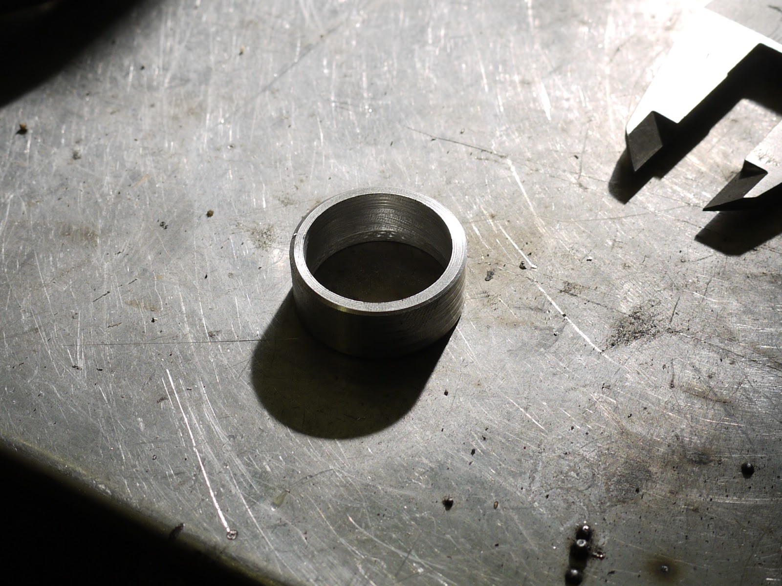
When I said, nothing fits with these yokes, I literally mean NOTHING. So the next step was to turn up a spacer ring for the upper yoke, so the stem is located properly.


The end-result is pretty convincing though, except for the stock bolt in the upper yoke it looks as stock as it can. 


A little note for the copy cats: Check the clearance of the lower yoke and don't have the stem sit flush in the yoke, but raise it a bit, otherwise you'll end up trimming the lower bearing cup holder on the frame a bit.