Thursday 25 November 2021

The XS Triple Sidecar - back to snowmobile carbs

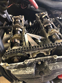
So I am going back to 31mm* snowmobile carbs and no it's not that I wasn't happy with the modified Gixxer flatslides, but to be honest I will need them next year on a mighty four that has been lurking way too long in another shed. (*Yes, previous iterations used 33mm snowmobile carbs, but I have sufficient carbs to make a 4-carb rack of those and only a single 31mm rack with three carbs, also torque is more important than outright horsepower on a sidecar once you reached a certain point.)

As usual they were properly mangled and not much use to me in their stock form.

This time I tackled the task differently than last time, because I wanted to use all the original inlets or at least the cast bosses as first I broke through the casting last time on one carb and second a fuel line in the way of the throttle cable during installation is no fun at all. 

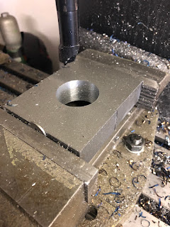
The one bit not shown is how I aligned the casting in the mill with a drill bit snuggly fitting into casting before milling the remnants of the pressed in fitting flat and then drilling it out.

Tapped M8x1.0 (standard hydraulics banjo bolt and banjo) and then after tapping gave it one more lick with a milling cutter to make sure the surfaces were square.


Milled down the boss on the left carb and there you go, enough room for the fitting. Don't think you could get it out with the carbs as a rack though. (But then again that was not the objective.) Also spot the challenge that came from turning a right into a left carb. The throttle-shaft hole is plugged.


Luckily in terms of the right carb, it is only plugged and can be knocked out with moderate force. (It's a nice press-fit though.)


It's a completely different story on the other end of the rack. Turning a left into a right carb involves a fair bit of thinking and machining. 

The first step was moderately easy once I summoned all my bravery to just drill into the casting. (As can be seen, I first tried to do a sort of lineboring job, but that didn't work, so I aligned a 16mm endmill with the casing and did what I had to do.)


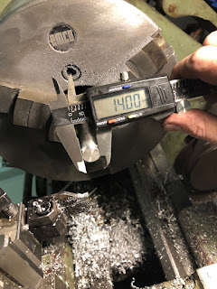
Fun starts with the insert that needs to go in there. Because it has to be an inside and outside press-fit and has not too much wall thickness left, so each of the two will affect each other, if I c*ck it up. (Spoiler from this point onwards I do consider myself a proper engineer.) So turn it to 16.55mm as the bore in the case is slightly out of round and measures 16.52mm at the widest point.

Then took the seal out of the carb body. It's a relatively normal 10x14x3mm lip-seal and if it weren't for a lockdown, I could buy one of these over the counter, if I screwed up. As can be seen, it checks out to 14.08mm and goes into a 14.00 hole. (So Mikunis press-fit was chosen a lot tighter than mine.)


Test fit on the lathe - wall thickness around 0.75mm (16.55-14.00mm) and yes, it distorts with the seal inserted. So I gave it another lick on the lathe and at least at that point it was round again.


Pressed into the casing, thanks to a light taper on the backside, it centered nicely and started with finger pressure.

Couple of tap-taps later and it sat all the way in and the shaft didn't bind up.


Making a solid 4mm tall, 14.00mm plug for a 13.95mm hole was almost relaxing at this point. Also, MGEHR-tools leave a beautiful finish. The 14.00mm were hit going straight down from 15.1x and this was the moment, when my ego politely pointed out that it was due for its own postcode.

Same trick, slight taper on the backside to get it started and the a few love taps to drive it all the way in afterwards.


The plan (obviously) was to use the throttle shaft I made for the Gixxer carbs and to be fair, I think that wasn't too outlandish to think it would work. Well, it didn't all holes are just a tad off to these. 

So I did it all again (sorry no photos, it's boring...)

Not sure, why I altered the throttle cable mount last time, but it clears just fine, so it'll stay (almost) stock.

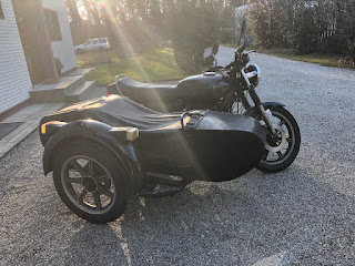
And that's the finished product - aside from painting the carb tops black and making an extension to the idle adjuster shaft. 


Fuel line is now a pretty straight forward affair and the horizontal section will be zip-tied to the rail.


So there you have it - bit more work necessary to get it finished and I have to come up with something smart regarding the throttle cable to give it the 90 bend it needs for perfection, but in all honesty this should be the hard part done.


Sunday 21 November 2021

The XS Triple Sidecar - unplanned maintenance

To be fair to the old girl right away, it was only unplanned, because I had originally expected to get through this Winter on the new sidecar. (Regardless of whether we're talking about the SR500 or the XV-sidecar.)

I checked the valves last year and the inlets were a bit on the tight side (I thought), but the exhaust valves, aside from the center cylinder one, were "about there". How wrong I was. For some weird reason I was absolutely convinced that on an Yamaha XS Triple, you run the common-place 0.10/0.15mm valve lash. For some reason today I decided to have a look into the book of lies and lo and behold it said 0.20/0.25mm, some frantic checking and rechecking of various resources on the net confirmed the finding and as a result making the notes below even more concerning.

How to read the chart, I and E stand for inlet and exhaust, the bottom number is the shim thickness installed, the number above is the initial valve clearance and the top value the valve clearance after the shim swap. Now I am in possession of a lovely box full of shims, but if you're not and check your valves, you go back to this handy chart and then can work out which shims to order.

So I rolled the old girl into the workshop, removed the fuel tank and got crackin'.


The big trick on an XS-Triple, you have to remove the camchain-tensioner, which usually ruins the paper gasket, but if you lubed that gasket up like this is part of some kinky massage-thingy, see below. 

Also when re-installing the tensioner, use the lock-bolt on the side to lock it into the rear-most position for easier installation.

With everything assembled and the sun slowly setting on the old girl, just one question remains:

Why hasn't anyone snatched this beauty up yet?

Saturday 20 November 2021

The SR500 sidecar build - bit of electrickery (part 7)

As other stuff kept me way busier than it should have, there's some left overs to report.

First of all as the old girl has got a busted 300 Ohm coil, I opted for a CDI Booster, which is a fancy way of naming an aftermarket CDI, which runs off the battery and not the stock coil inside the alternator. 

And the other thing I wanted to share was a neat little trick that I saw a few years ago on some construction equipment (and a similar fix can be found on the old TR1). If you have the tail-light wiring run on the underside of the rear mudguard, use some thick-wall fuel hose for protection.


Doesn't look like much, but those cables are well protected and weather-proofed. And that was it for this week, I hope that the next posts will bring a bit more on the subject of sidecar mounts and electro-plating.


Thursday 11 November 2021

The SR500 sidecar build - sidecar mounts (part 6)

The first part of this post will look a bit like engineering class, introduction to parts layout and fixturing. Just to give you a few specs: The block below is 80x100x25mm - comprising of two 40x50mm firmly pressed together with a 38.5mm bore in the middle. 

Step one (after clamping everything in a vise), mark the center. Also if you wonder what the washer is doing there - if you hold parts in a vise and for whatever reason couldn't square it up beforehand, it is a clever idea to just press on it in a single point. (Some people use a ball from a ball bearing or the like to just push against a single point.)

Then I marked the hole I planned to bore just to check once more, if everything would fit.

And then get started with drilling a hole as big as my drills would allow. Mainly because drilling is a lot faster than boring with the boring bar.

Remember the boring bar from the last post, guess who's going to play a VERY prominent role in the rest of this post. 


In order to maintain alignment prior to drilling the holes for the mounting bolts as the parts are clearly too tall clamp them in one go and measuring and finding the holes again is prone to errors.

Which brings us to a classic do as I say, not as I do moment... or in other words, don't get overly excited. A knife-head makes short work of squaring up the part and leaves a remarkably nice finish.

Oh and it fits, but the two halves are almost touching, not allowing for much clamping force.

Bit of extra clearance is easy, took about 0.5mm off the inner faces and now there's plenty of room for clamping the tube so hard one could probably squish it in between. 

As I had some alignment issues and no long enough bolts, I only drilled and tapped the block for M6 bolts. Ultimately M10x100 bolts will be used.

And then the same had to be repeated for four more blocks. Which is where I found out that the sweet spot for this mill and boring bar combination was at an incredible 2100rpm and a 3mm feed on the diameter, which resulted in those lovely straw-coloured chips.

 Not the block from the picture, but to give you an idea how all of this went down and why I was so impressed with that little 6x26 mill.

I know you're supposed to either run inserts dry or flood cool them, but a bit of oil on the surface did help tremendously.

Also, if you clean up a part with brake-cleaner and then tack it... well, you may end up with a bit of a fire hazard. 

And that's the first of the blocks finished, as far as purely functional features are concerned. Held together by two M10x60 bolts.

So just have to do this three more times.

Now regarding the blocks the three things left to do are to test fit them, make them look a bit less square, pointy and sharp edged and then zinc-plate them.