
In order to be less of a hassle down the road the first thing that I wanted to address was the location of the center stand spring as I plan to route the exhaust through there just as I did on my TR1.

The other thing was the fact that the frame with some other bits being
repainted now, looked a lot worse for wear in comparison, so a bit of fresh
paint was due...

... and then put the tag back on.

And once the frame was re-assembled, I really wanted to use those XS750/850 headlight ears, but I was lacking the correct size locating rings...


... and if you thought that by now it was really well about time to dig into the wiring: WRONG. As the timing marks between crank- and intermediate-pulley didn't line up (mind you, I probably just didn't turn the engine over often enough and was overly worried about making mistakes), I pulled the head and cylinder and retimed everything.


And then after having them soaked in engine oil for about 2-3 days, I also completed the clutch, while I was at it.

With that out of the way, it was time to turn my attention to the loom. There's two main areas of concern: first is to remove a set of safety cut-out relays as they were specifically made for Yamaha and are no longer available new and as all old electronics they don't exactly become more reliable with age. (On the right end of the picture - the pair of golden relays.)

Once you unwrap this section of the loom, it becomes pretty obvious that the first relay just loops the red-white (ignition +) cable to the second relay.
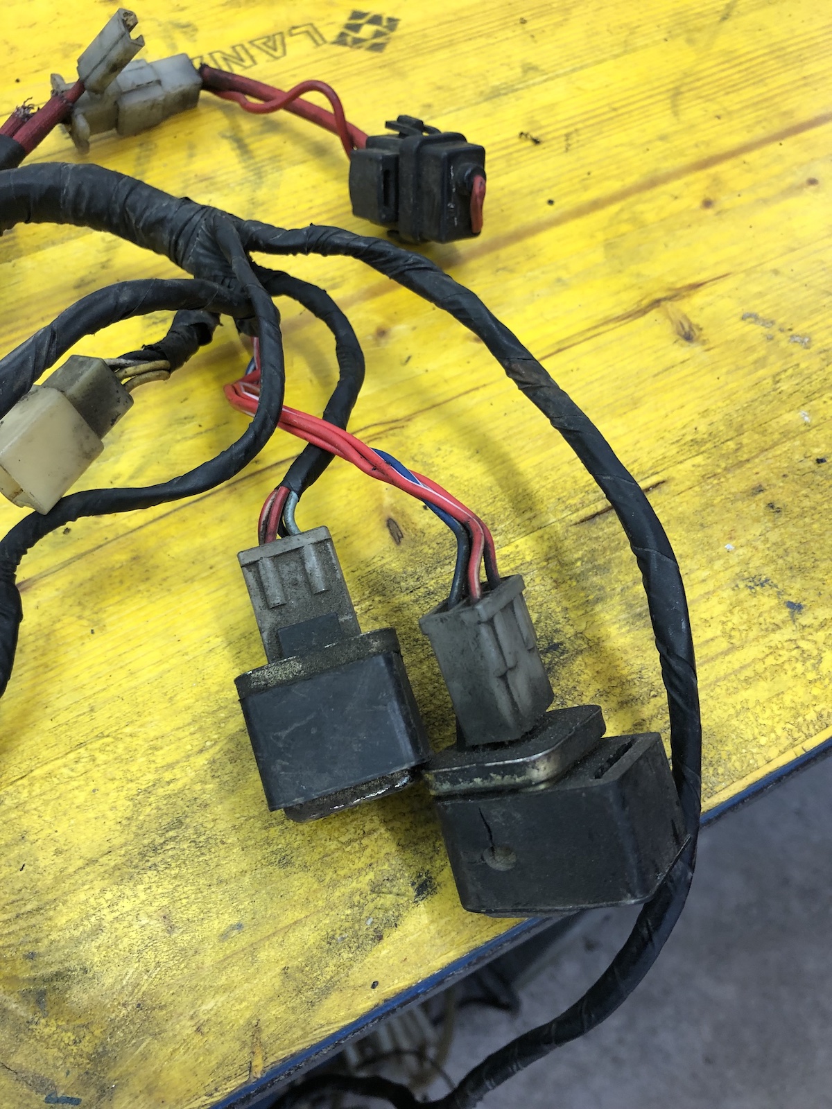

This basically means the second one is the one, which does all the "cutting-out-or-not" work. The light blue cable is from the neutral switch, the blue and yellow one from the clutch-switch. As such the extra wire from the y-section of the neutral switch can go.

Ultimately you end up with these four wires, where the most important thing to know is, that the one red-white cable that comes down from the kill-switch and is hot (unless the kill-switch is engaged) goes to yellow. Blue-white is the trigger-wire for the starter solenoid.

Next to these two relays is an unused triple-plug, which is used for the automatic indicator cancelling unit and is equally superfluous, of which the green white cable goes to the speedo and the other two go to the light switch (where the pin is blank on European market models) and the flasher relay, where it is usually looped onto itself. This is really just to remove some excess cables.
The second and more important mod (to me) is to run a separate cable from the ignition box to the tach, which comes in handy when running an aftermarket box like a ignitech, but the stock boxes can be modified very easily and from the last three or four years experience this actually helped with the longevity of those tachs.

Next up will be throwing all of this onto the frame and hoping that it will stick...
No comments:
Post a Comment