
First, the schematic and the two following pictures are what it'll look like in real life.


That said, if your TR1's wiring harness is in good condition you may find these three pictures quite helpful:


Now if you wanted to do it really cheap and easy, you could just pull this cable out of the plug and put it where the red and white u-cable would go and call it a day. In my case I wanted to deal with some other issues of wear and tear on the wiring harness and most importantly run the tach off the dedicated pin on the Ignitech TCI-unit.
On the Ignitech-side this is dead simple. Check out the pin-out diagram on the Ignitech homepage and find Pin 15 (it's the most center one, which is empty, and sits between a red and two blue cables and run it to the last remaining empty plug-hole on the connector to the wiring harness. Ignitech suggests using yellow-green cable and ideally you would want to go for 0.75 or 1.00mm cable as the pin on the TCI isn't made for heavy gauge cable.

Here you can see a slightly altered wiring harness, with the most major alterations being two adapter cables for the cables to the starter solenoid and oil-level switch as in stock form they are too short and as a result you have to take off the right foot-peg-holder, which is a bit of a pain.

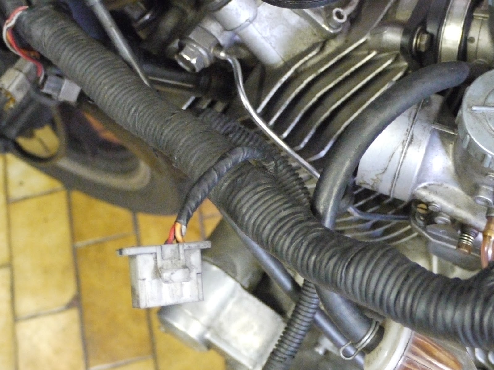
Now this is the 6-pin connector to the wiring harness and in order to alter the tach's wiring this is where you have to remove the insulating tape and work your way to the front and find the soldered Y-joint of the orange cable. The one going to the headlight shell is the one going to the cockpit and it needs a cable soldered on and then routed to the 6-pin connector.

The pictures don't show it too well, but the rear half of the wiring loom is now roughly half the diameter with all the cabling removed.
There's actually two more cables that can be removed: white-green and black-yellow. The first being used for the auto-cancellation of the indicators and the latter for the clutch-lever-switch.


I love to use silk-coroplast-type tape to wrap my looms, because it's very durable AND it does look rather professional, if I may so.

And that's the amount of stuff that's left over plus all the old insulating tape...

Hi, I figured that this post is about 2 years old. However I need to get in touch with you about this Wire Harness unit. My father has left me a legacy (Motorcycle of his a 1993 model XV Virago 1100) but its been years I did not used and the workshop discovered that the "CDİ İgnition unit J4T031" is fine ! However, the Wire Harness unit has been damaged ! Can you help me out please. Thank you 09emreeren@gmail.com
ReplyDelete